Keszoox
SRD-05/12/24VDC 5-Pin 10A Relay | SRD-SL-C | DC Electromagnetic Switch | SPDT | PCB Mount
SRD-05/12/24VDC 5-Pin 10A Relay | SRD-SL-C | DC Electromagnetic Switch | SPDT | PCB Mount

Couldn't load pickup availability
SRD-05/12/24VDC 5-Pin 10A Relay — SRD-SL-C | SPDT | PCB Mount | DC Electromagnetic Switch
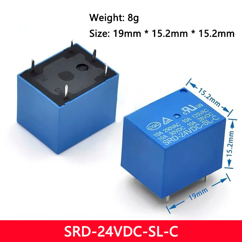
The SRD series 5-pin PCB mount relay is the most commonly used general-purpose relay in Arduino relay modules, home automation controllers, and industrial control circuits. The SPDT (Single Pole Double Throw) contact configuration provides both normally-open (NO) and normally-closed (NC) switching in a single relay, enabling both make-on-energise and break-on-energise circuit configurations. Available in 5V, 12V, and 24V coil voltage versions to match your control circuit supply voltage. Rated for AC 250V/10A and DC 30V/10A load switching — suitable for mains lighting, motors, heaters, and DC loads.
Specifications
| Model | SRD-SL-C (SRD series) |
| Coil Voltage | 5V DC / 12V DC / 24V DC (as selected) |
| Contact Configuration | SPDT (1 Form C: NO + NC + COM) |
| Pin Count | 5 pins (2 coil + 3 contact) |
| Max AC Load | AC 250V / 10A |
| Max DC Load | DC 30V / 10A |
| Mount Type | PCB mount (DIP, through-hole) |
| Package | DIP |
| Origin | Mainland China |
Pin Configuration (5-Pin SRD)
| Pin | Function |
|---|---|
| Pin 1 | Coil − (negative) |
| Pin 2 | Coil + (positive) |
| Pin 3 | COM (common contact) |
| Pin 4 | NC (normally closed — connected to COM when relay OFF) |
| Pin 5 | NO (normally open — connected to COM when relay ON) |
SPDT Contact Configuration — How to Use
| Contact | Relay OFF (coil de-energised) | Relay ON (coil energised) |
|---|---|---|
| COM – NO | Open (circuit broken) | Closed (circuit made) |
| COM – NC | Closed (circuit made) | Open (circuit broken) |
Use COM–NO for “normally off, switch on” applications (e.g., turn on a light when relay activates). Use COM–NC for “normally on, switch off” applications (e.g., fail-safe circuits that open on relay activation).
Key Features
- ✅ SPDT configuration — both NO and NC contacts available for maximum circuit flexibility
- ✅ AC 250V / 10A load rating — switches mains lighting, motors, and heaters
- ✅ DC 30V / 10A load rating — switches DC motors, solenoids, and high-current DC loads
- ✅ 5V / 12V / 24V coil options — matches Arduino (5V), automotive (12V), and industrial (24V) control voltages
- ✅ PCB mount DIP package — direct PCB soldering, compatible with standard relay module PCBs
- ✅ SRD-SL-C series — the standard relay used in widely-available Arduino relay module boards
Common Applications
- Arduino relay module replacement relay
- Home automation mains switching (lights, fans, appliances)
- Industrial control panel relay
- Motor starter and contactor auxiliary relay
- Alarm system output relay
- Automotive relay (12V version)
- HVAC control relay
- Custom relay board design
Coil Drive Requirements
The relay coil requires sufficient current to energise reliably:
| Coil Voltage | Coil Resistance (typical) | Coil Current (typical) |
|---|---|---|
| 5V | ~70Ω | ~70mA |
| 12V | ~400Ω | ~30mA |
| 24V | ~1600Ω | ~15mA |
Arduino GPIO pins are limited to 40mA. Always drive relay coils via a transistor or relay driver IC (e.g., ULN2003) — do not connect relay coils directly to Arduino GPIO pins.
Frequently Asked Questions
Q: Can I connect this relay directly to an Arduino GPIO pin?
A: No. The 5V relay coil draws ~70mA, exceeding the Arduino GPIO pin’s 40mA limit. Use a transistor (e.g., 2N2222, BC547) or a relay driver module with optocoupler isolation to drive the relay from an Arduino GPIO pin.
Q: Is a flyback diode required?
A: Yes. Always connect a flyback diode (e.g., 1N4007) across the relay coil terminals (cathode to positive, anode to negative) to suppress the back-EMF spike when the relay de-energises. Most relay module boards include this diode.
Package Contents
- 1× SRD-SL-C 5-Pin PCB Mount Relay (coil voltage as selected: 5V / 12V / 24V)