Skip to product information
1 of 8

Keszoox

XH-M131 Light Control Photoresistor Relay Module 5V/12V/24V Automatic Brightness Detection Switch 10A

XH-M131 Light Control Photoresistor Relay Module 5V/12V/24V Automatic Brightness Detection Switch 10A

Regular price $5.72 USD
Regular price $0.00 USD Sale price $5.72 USD
Save Liquid error (snippets/price line 136): divided by 0% Sold out
Taxes included. Shipping calculated at checkout.
Color
visa
View full details
  • ★Product Description
  • ★About us
  • ★Custom cable

SPECIFICATIONS

Application: Computer

Brand Name: OLNYLO

Condition: New

High-concerned chemical: None

Model Number: XH-M131

Operating Temperature: -20+50

Origin: Mainland China

Supply Voltage: 5V / 12V / 24V

Type: Relay

is_customized: Yes

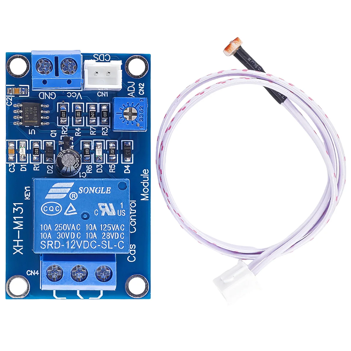
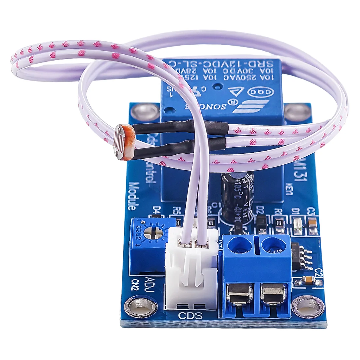
XH-M131 DC 5V 12V 24V Light Control Switch Photoresistor Relay Module Detection Sensor 10A Brightness Automatic Control Module

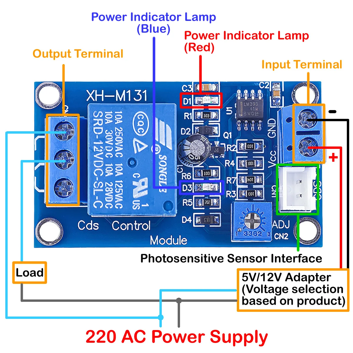
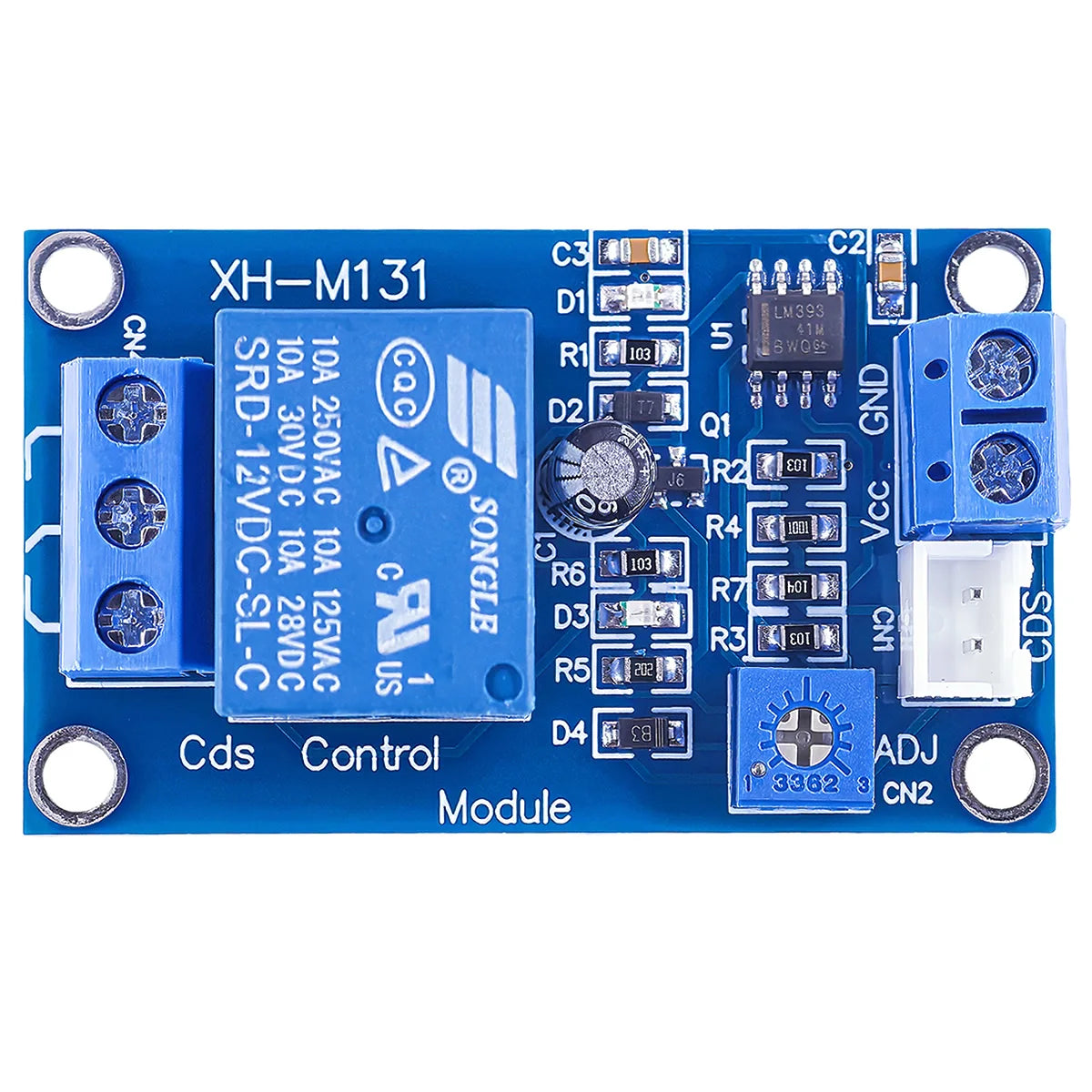
This module can be used for light detection and brightness detection. It has a power indicator (red) and a relay pull in indicator (blue), and is equipped with four M3 screw mounting holes, which greatly facilitates installation. The board can adjust the photosensitivity through a potentiometer. It has a relay, which can be used as a variety of brightness detection control switches, such as street lamps, which can be automatically turned on at night, turned off at day, and other equipment that needs automation.

Input: DC 5V / 12V
Load capacity: 10A / AC 250V or DC up to 30V
RED LED ON: Indicate the Power ON
BLUE LED ON: Relay is working
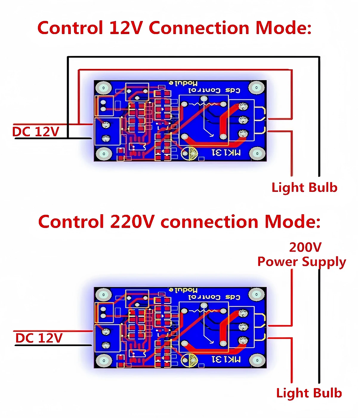
Module output terminal has three ports
Normally open ( NO )
Common terminal ( COM )
Normally closed ( NC )
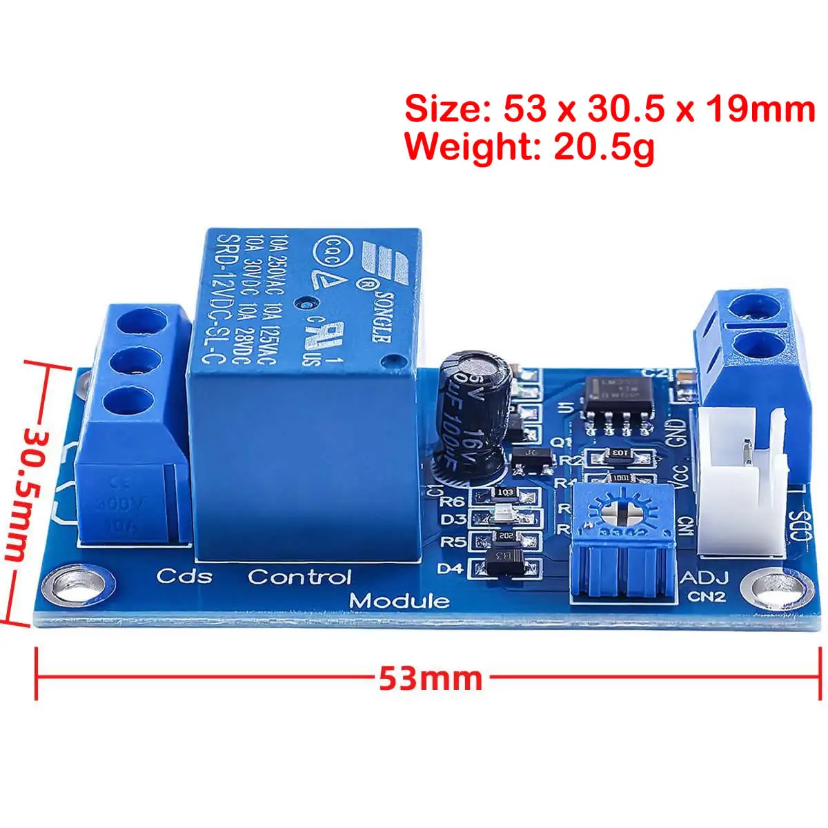
Size: 53*31*19mm
Light threshold can be adjusted by potentiometer to set the relay start

Parameters:
1. The module adopts 12V power supply, with anti reverse connection function, and the reverse connection power will not damage the module;
2. Large load capacity of normally open interface: AC 0V-125V/20A, DC 0V-14V/20A; The output end of the module has three ports: common end (COM), normally open (CK) and normally closed (CB). The three ports are equivalent to a dual control switch. When the relay coil is powered, the common end is connected to the normally open end. When there is no power, the common end is connected to the normally closed end. The COM end is generally connected to the negative power supply through the load, and the normally open end is connected to the positive power supply.
3. The sensitivity can be adjusted through the potentiometer, and the threshold value of the starting relay can be set by adjusting the potentiometer. When the light is darker than the threshold value, the module relay is pulled in, and when the light is brighter than the threshold value, the relay is disconnected;

 
Instructions:
1. The photoresist module is most sensitive to the brightness of the ambient light, and is generally used to detect the brightness change of the ambient light.
2. When the ambient light of the module is darker than the threshold value, the relay is pulled in, and the common end is connected with the normally closed end (disconnected from the normally closed end). When the external ambient light is brighter than the set threshold value, the relay is disconnected, and the common end is disconnected from the normally closed end (disconnected from the normally closed end)
3. Common terminal, normally open, normally closed, the three ports are equivalent to a double control switch. When the relay coil is energized, the common terminal is connected with the normally open terminal, and when there is no power, the common terminal is connected with the normally closed terminal.
 
Description of Potentiometer Indicator:
Red light: module working voltage,
Blue light: relay working indicator
Potentiometer: adjust detection brightness value
Installation wiring (take the control of street lamps as an example)
 
Matters Needs Attention:
1. If you need to work at night and do not work during the day, please connect the common terminal and the normally open terminal, such as street lamp control. Otherwise, connect the common terminal and the normally closed terminal. (Please select port wiring according to actual needs)
2. One contact in the middle of the output terminal is the normally closed terminal below the common terminal, and the upper one is the normally open terminal.

  • ♥Hear From Our Happy Customers
  • ♥Verified Buyer Reviews
  • ♥Trusted by Professionals and Engineers