Keszoox
ESP8266 WiFi Module — ESP-12E / ESP-12F / ESP12S, 802.11 b/g/n, Arduino & IoT
ESP8266 WiFi Module ESP-12E / ESP-12F / ESP12S, 802.11 b/g/n, Arduino & IoT

Couldn't load pickup availability
ESP8266 WiFi Module — ESP-12E / ESP-12F / ESP12S, 802.11 b/g/n, Arduino & IoT
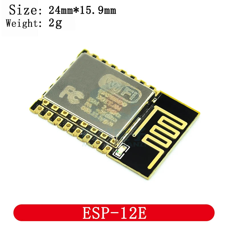
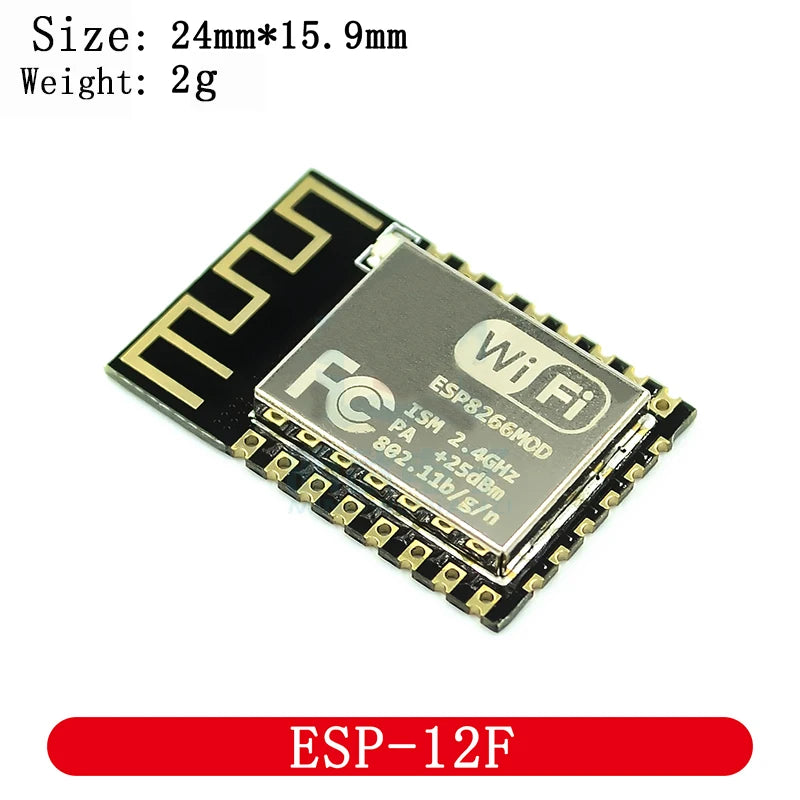
The ESP-12E, ESP-12F, and ESP12S are compact SMD WiFi modules built around the Espressif ESP8266EX SoC, providing 802.11 b/g/n WiFi connectivity with an integrated TCP/IP stack, GPIO, ADC, SPI, I²C, and UART. With 4MB flash (ESP-12F/ESP12S) and a PCB trace antenna, they are the core module used in NodeMCU, Wemos D1 Mini, and countless custom IoT designs. Programmable via Arduino IDE, MicroPython, or AT commands.
Key Specifications
| Parameter | Value |
|---|---|
| SoC | Espressif ESP8266EX |
| WiFi Standard | 802.11 b/g/n, 2.4GHz |
| Flash Memory | 1MB (ESP-12E) / 4MB (ESP-12F, ESP12S) |
| GPIO Pins | 11 (ESP-12E/F) / 9 (ESP12S) |
| ADC | 1× 10-bit (0–1V input range) |
| Interfaces | UART, SPI, I²C, PWM, I²S |
| Supply Voltage | 3.0V – 3.6V (3.3V nominal) |
| Peak Current | ~300mA (WiFi TX) |
| Antenna | PCB trace antenna (onboard) |
| Pin Pitch | 2mm (castellated pads) |
ESP-12E vs ESP-12F vs ESP12S
| Feature | ESP-12E | ESP-12F | ESP12S |
|---|---|---|---|
| Flash | 1MB | 4MB | 4MB |
| GPIO count | 11 | 11 | 9 |
| Antenna | PCB trace | Improved PCB trace | PCB trace |
| RF performance | Standard | Better (−1dB improvement) | Standard |
| Best for | Basic IoT, AT command use | OTA updates, larger sketches | Compact designs, fewer GPIOs needed |
Why Choose ESP-12E/F/ESP12S?
- 4MB flash (ESP-12F/ESP12S) — sufficient for OTA firmware updates and large Arduino sketches
- Full Arduino IDE support — program with familiar Arduino syntax using ESP8266 board package
- Integrated TCP/IP stack — no external WiFi chip needed, handles HTTP, MQTT, WebSocket natively
- 11 GPIO pins — enough for most IoT sensor and actuator applications
- 2mm castellated pads — can be soldered directly to custom PCBs or used with 2mm-to-2.54mm adapter
Compatible With
- Arduino IDE: ESP8266 board package (Board Manager URL: http://arduino.esp8266.com/stable/package_esp8266com_index.json)
- MicroPython: Official ESP8266 MicroPython firmware (esptool.py flash)
- NodeMCU Lua: NodeMCU firmware with Lua scripting
- AT Commands: Default Espressif AT firmware for modem-style WiFi control from external MCU
- Home Assistant / ESPHome: ESPHome firmware for direct smart home integration
- Programmer: USB-to-UART adapter (CH340G, CP2102) + esptool.py
Frequently Asked Questions
Q: How do I program ESP-12E/F with Arduino IDE?
A: (1) Install ESP8266 board package in Arduino IDE. (2) Connect GPIO0 to GND (flash mode), GPIO15 to GND, GPIO2 to VCC. (3) Connect UART TX/RX to CH340 or CP2102 adapter. (4) Power with stable 3.3V/500mA supply. (5) Upload sketch. (6) Disconnect GPIO0 from GND and reset for normal boot. Use a NodeMCU or Wemos D1 Mini board for easier programming without manual GPIO wiring.
Q: What power supply do I need for ESP-12F?
A: ESP8266 requires 3.3V with up to 300mA peak current during WiFi transmission. Use a dedicated 3.3V/500mA LDO (AMS1117-3.3, LD1117-3.3) or a switching regulator. Do not power from Arduino’s 3.3V pin — it is typically limited to 50–150mA and will cause brownout resets during WiFi TX.
Q: What is the difference between ESP-12F and NodeMCU?
A: ESP-12F is the bare WiFi module with 2mm castellated pads — requires external USB-UART, 3.3V regulator, and boot mode resistors for programming. NodeMCU is a development board that integrates ESP-12E/F with a CH340 USB-UART, 3.3V regulator, and all boot resistors, making it plug-and-play for USB programming. Use ESP-12F for custom PCB designs; use NodeMCU for prototyping.
Package Contents
- 1× ESP8266 WiFi Module (ESP-12E / ESP-12F / ESP12S — variant as selected)