Keszoox
74HC14D Hex Schmitt Trigger Inverter — SOP-14 SMD, 2–6V, -40°C to 125°C (5-Pack)
74HC14D Hex Schmitt Trigger Inverter SOP-14 SMD, 2–6V, -40°C to 125°C (5-Pack)

Couldn't load pickup availability
74HC14D / SN74HC14DR Hex Schmitt Trigger Inverter — SOP-14 SMD, 2–6V (5-Pack)
The 74HC14D (SN74HC14DR) contains six independent Schmitt trigger inverters in a SOP-14 SMD package. Unlike standard inverters, each gate has hysteresis (typically 0.9V at 5V supply) that makes the output switching threshold different for rising and falling inputs. This hysteresis eliminates false triggering from slow-rising signals, noise, and contact bounce, making it the standard IC for signal conditioning, button debouncing, RC oscillators, and noise-immune logic interfacing.
Key Specifications
| Parameter | Value |
|---|---|
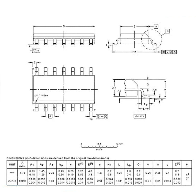
| Package | SOP-14 (SMD) |
| Gates | 6× Schmitt trigger inverter |
| Logic Family | 74HC (High-Speed CMOS) |
| Supply Voltage | 2V – 6V |
| Hysteresis (VCC=5V) | ~0.9V typ. (VT+ ≈ 2.9V, VT− ≈ 2.0V) |
| Output Drive Current | ±25mA per output |
| Propagation Delay | ~13ns (VCC=5V) |
| Operating Temperature | -40°C to +125°C |
| Quantity | 5 pieces |
Schmitt Trigger vs Standard Inverter
| Feature | Schmitt Trigger (74HC14) | Standard Inverter (74HC04) |
|---|---|---|
| Switching threshold | Hysteresis (VT+ ≠ VT−) | Single threshold (~50% VCC) |
| Noise immunity | High (rejects noise within hysteresis band) | Low (any noise near threshold causes glitch) |
| Slow signal handling | Clean output from slow-rising input | Multiple transitions on slow input |
| Best for | Noisy signals, RC oscillator, debounce | Clean digital signals only |
Why Choose 74HC14D?
- Schmitt trigger hysteresis — ~0.9V hysteresis at 5V eliminates false triggering from noise and slow signals
- 6 inverters per IC — six independent Schmitt trigger inverters in one SOP-14 package
- RC oscillator — one inverter + R + C forms a simple square wave oscillator
- Button debouncing — RC + Schmitt trigger eliminates contact bounce without software debounce
- SOP-14 SMD — compact footprint for PCB designs
Compatible With / Common Use Cases
- RC oscillator: One 74HC14 inverter + R (10kΩ) + C (10nF) = ~10kHz square wave oscillator (f ≈ 1/(1.2×R×C))
- Button debounce: RC filter (10kΩ + 100nF) on button input, then through 74HC14 — clean digital output without bounce
- Signal conditioning: Convert slow-rising analog-like signals (thermistor, photodiode) to clean digital edges
- Crystal oscillator buffer: Buffer crystal oscillator output for distribution to multiple logic circuits
- Noise-immune input: Interface noisy industrial sensors to clean CMOS logic
Frequently Asked Questions
Q: How do I build an RC oscillator with 74HC14?
A: Connect a resistor R from the output of one inverter back to its input. Connect a capacitor C from the input to GND. The oscillation frequency is approximately f = 1 / (1.2 × R × C). For R=10kΩ, C=10nF: f = 1 / (1.2 × 10000 × 0.00000001) = ~8.3kHz. Use a second inverter to buffer the output for a clean square wave drive.
Q: What is the difference between 74HC14 (SOP-14) and 74HC14N (DIP-14)?
A: 74HC14D is the SOP-14 SMD package (surface mount). 74HC14N is the DIP-14 through-hole package. Both have identical electrical specifications — the only difference is the physical package. Use DIP-14 for breadboard prototyping; use SOP-14 for PCB designs.
Q: Can 74HC14 debounce a mechanical switch without software?
A: Yes — connect a 10kΩ pull-up resistor from VCC to the switch input, and a 100nF capacitor from the switch input to GND. Connect the switch between input and GND. Feed the RC-filtered signal into a 74HC14 inverter. The RC time constant (10kΩ × 100nF = 1ms) filters bounce pulses, and the Schmitt trigger provides a clean digital output. The output is inverted — add a second inverter stage if non-inverted output is needed.
Package Contents
- 5× 74HC14D / SN74HC14DR Hex Schmitt Trigger Inverter IC (SOP-14)