


8-Channel Relay Module 5V — 10A SPDT, Active-Low, Opto-Isolated, Arduino Compatible
8-Channel Relay Module 5V 10A SPDT, Active-Low, Opto-Isolated, Arduino Compatible
Compatible JST cables for sensors and modules — secure & reliable. Shop now.

Couldn't load pickup availability
8-Channel Relay Module — 5V, 10A SPDT, Active-Low, Opto-Isolated
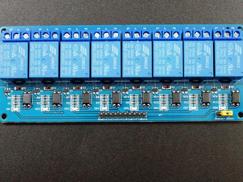
The 8-channel 5V relay module provides eight independently controlled SPDT relays on a single PCB — the standard solution for Arduino and ESP32 home automation projects requiring control of multiple AC or DC loads simultaneously. Each relay is driven by an onboard transistor and opto-isolator, requiring only <5mA from each GPIO pin to switch a 10A load. All eight relays can be energized simultaneously, drawing ~600mA total from the 5V supply.
The JD-VCC jumper allows the module to operate in two modes: standard mode (jumper installed, single 5V supply) or fully opto-isolated mode (jumper removed, separate 5V supply for relay coils) for maximum protection against AC-side faults.
Key Features
- 8 independently controlled SPDT relays — IN1–IN8, each independently addressable
- 10A SPDT contacts — switches up to 250VAC @ 10A or 15VDC @ 10A per channel
- Active-LOW control — logic LOW energizes relay; logic HIGH de-energizes
- Opto-isolated inputs — complete electrical isolation between MCU and relay power
- JD-VCC jumper — selectable single-supply or dual-supply (full isolation) mode
- <5mA GPIO drive — safe for all Arduino, ESP32, and Raspberry Pi GPIO pins
- Red LED indicators — one per channel, illuminates when relay energized
- Built-in flyback diodes — protects driver transistors from relay coil back-EMF
- 4 × M3 mounting holes — for secure enclosure mounting
Technical Specifications
| Supply Voltage | 5V DC |
| Supply Current | ~70mA per relay energized (~600mA all 8 on) |
| Control Logic | Active-LOW (LOW = relay ON) |
| Logic HIGH threshold | >2.8V |
| Logic LOW threshold | <1.2V |
| GPIO Current Required | <5mA (opto-isolated driver onboard) |
| Relay Contact Rating (AC) | 115VAC @ 10A / 250VAC @ 10A |
| Relay Contact Rating (DC) | 15V DC @ 10A (recommended max) |
| Relay Type | SPDT (NO + NC + COM) per channel |
| PCB Dimensions | 138 × 56 × 20mm (5.4 × 2.2 × 0.79″) |
Wiring Guide
Control header (1×10):
- GND → Arduino/MCU GND (must share ground)
- IN1–IN8 → Arduino digital output pins (LOW = relay ON)
- VCC → 5V supply
Isolation header (1×3):
- JD-VCC → Relay coil power. Jumper to VCC for single-supply mode (default). Remove jumper, connect separate 5V for full opto-isolation.
- VCC → Logic supply (same as control header VCC)
- GND → Ground for separate relay supply (if used)
Load screw terminals (per channel): NO / COM / NC — same as 1-channel module.
Opto-Isolation Modes
- Standard mode (jumper installed): JD-VCC tied to VCC — single 5V supply powers both logic and relay coils. Opto-isolators still present but not providing full isolation. Easiest setup.
- Full isolation mode (jumper removed): Separate 5V supply connected to JD-VCC powers relay coils independently. MCU logic circuit is fully isolated from relay power — maximum protection against AC-side faults, lightning strikes, or load failures.
DC Voltage Limit
Relay contacts are rated 30VDC on the relay body, but DC arc suppression is poor above ~15V. Limit DC switching to 15V or below. AC performance is excellent — tested at 1500W / 12.5A heater load without issues.
Typical Applications
- Arduino / ESP32 home automation — control 8 lights, fans, or appliances from a single board
- Smart home relay controller — MQTT / Home Assistant / Node-RED integration
- Irrigation system — control 8 solenoid valves for zone-based watering
- Industrial PLC output expansion — 8-channel relay output card
- Greenhouse automation — lights, heaters, fans, misters, CO₂ valves
- 3D printer enclosure control — lights, exhaust fan, filament dryer
- Escape room and prop control — 8 independently triggered effects
Package Contents
- 1 × 8-Channel Relay Module 5V (10A SPDT, active-low, opto-isolated, with screw terminals)


Blog posts
View all-

Best JST Connector Crimping Tools in 2026: Engi...
Choosing the wrong crimping tool ruins JST connectors and wastes wire. This guide compares the top crimping tools for JST SH, GH, PH, XH, and VH series — including Engineer...
Best JST Connector Crimping Tools in 2026: Engi...
Choosing the wrong crimping tool ruins JST connectors and wastes wire. This guide compares the top crimping tools for JST SH, GH, PH, XH, and VH series — including Engineer...
-

Molex KK 254 vs Mini-Fit Jr. vs Micro-Fit 3.0: ...
Choosing between Molex KK 254, Mini-Fit Jr., and Micro-Fit 3.0? This guide compares pitch, current rating, locking mechanism, wire gauge, and typical applications — with decision tables, part number references,...
Molex KK 254 vs Mini-Fit Jr. vs Micro-Fit 3.0: ...
Choosing between Molex KK 254, Mini-Fit Jr., and Micro-Fit 3.0? This guide compares pitch, current rating, locking mechanism, wire gauge, and typical applications — with decision tables, part number references,...
-

DuPont Connector vs JST PH 2.0: Pinout, Specs &...
Not sure whether to use a DuPont 2.54mm or JST PH 2.0mm connector? This guide compares pitch, locking mechanism, current rating, pinout, and best use cases — so you can...
DuPont Connector vs JST PH 2.0: Pinout, Specs &...
Not sure whether to use a DuPont 2.54mm or JST PH 2.0mm connector? This guide compares pitch, locking mechanism, current rating, pinout, and best use cases — so you can...


