Keszoox
IRFZ44N TO-220 N-Channel MOSFET 55V 49A Field Effect Transistor
IRFZ44N TO-220 N-Channel MOSFET 55V 49A Field Effect Transistor

Couldn't load pickup availability
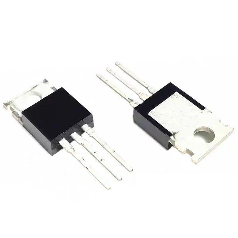
IRFZ44N TO-220 N-Channel Power MOSFET — 55V / 49A / 17.5mΩ
The IRFZ44N is a popular N-channel power MOSFET in TO-220 package, widely used in hobbyist and professional power electronics for its combination of moderate current rating (49A), low on-resistance (17.5mΩ), and near-logic-level gate threshold voltage — making it easier to drive from 5V microcontroller circuits than higher-threshold MOSFETs like the IRF3205. It is one of the most commonly specified MOSFETs in Arduino motor control, PWM dimmer, and switching power supply projects.
Available in 5-piece or 10-piece packs.
Key Specifications
- Part Number: IRFZ44N / IRFZ44NPBF
- Channel Type: N-Channel
- Package: TO-220 (through-hole, tab = Drain)
- Drain-Source Voltage (Vds): 55V
- Continuous Drain Current (Id): 49A @ 25°C (35A @ 100°C)
- On-Resistance Rds(on): 17.5mΩ @ Vgs=10V
- Gate Threshold Voltage (Vgs(th)): 2V – 4V (logic-level compatible)
- Total Gate Charge (Qg): 180nC @ Vgs=10V
- Power Dissipation (Pd): 94W (with heatsink)
- Body Diode Forward Voltage: 1.4V @ 25A
- Operating Temperature: −55°C to +175°C
- Quantity: 5 or 10 pieces (select variant)
TO-220 Pinout
- Pin 1 (left): Gate (G)
- Pin 2 (center): Drain (D)
- Pin 3 (right): Source (S)
- Tab (metal): Drain (D) — use insulating pad when mounting to grounded heatsink
Gate Drive from Arduino / 5V MCU
The IRFZ44N has a gate threshold of 2–4V, meaning it begins to turn on at ~2V and is partially enhanced at 5V. However, for full Rds(on) = 17.5mΩ, Vgs = 10V is required. For Arduino PWM motor control at moderate currents (≤10A), 5V gate drive is often acceptable with the understanding that Rds(on) will be higher (~30–50mΩ at Vgs=5V).
- For currents ≤10A: Direct Arduino GPIO drive (5V) is workable for low-frequency PWM (≤1kHz)
- For currents >10A or high-frequency PWM: Use a gate driver IC (IR2104, TC4420, UCC27524) to achieve 10V Vgs and fast switching
- Gate resistor: Add 10–22Ω series gate resistor to limit switching speed and reduce ringing
- Flyback diode: Always add a flyback diode (1N4007 or Schottky) across inductive loads (motors, solenoids, relays)
Arduino PWM Motor Control Wiring
- Gate (G, pin 1) → Arduino PWM pin (via 10Ω–100Ω resistor)
- Drain (D, pin 2) → Motor negative terminal
- Source (S, pin 3) → GND
- Motor positive terminal → 12V supply
- Flyback diode: cathode to 12V, anode to motor negative terminal (across motor)
- Add 10kΩ pull-down resistor from Gate to Source to ensure MOSFET is OFF when Arduino pin is floating
IRFZ44N vs. IRF3205 vs. IRF540N
- IRFZ44N: 55V, 49A, 17.5mΩ, Vgs(th) 2–4V. Best for Arduino/5V MCU projects at moderate current. Easier to drive.
- IRF3205: 55V, 110A, 8mΩ, Vgs(th) 2–4V. Higher current, lower Rds(on). Better for high-current inverters and motor drives. Requires 10V gate drive for full performance.
- IRF540N: 100V, 33A, 44mΩ. Higher voltage rating for 48V–72V bus applications. Higher Rds(on).
Typical Applications
- Arduino PWM DC motor speed control (12V motors up to 10–20A)
- PWM LED dimmer (12V/24V LED strips, high-power LEDs)
- Solenoid and relay driver (12V/24V coils)
- Low-side switch for 12V/24V loads controlled by microcontroller
- DC-DC buck converter low-side switch
- Battery discharge switch in BMS circuits
- Electronic load (constant current sink for battery testing)
- H-bridge motor driver (low-side N-channel, paired with P-channel high-side)
Package Contents
- 5 or 10 × IRFZ44N TO-220 N-channel power MOSFET (quantity as selected)