


Keszoox
2-Channel Relay Module 5V / 12V / 24V | Optocoupler Isolated High/Low Trigger | AC 250V 10A | Arduino
2-Channel Relay Module 5V / 12V / 24V | Optocoupler Isolated High/Low Trigger | AC 250V 10A | Arduino

Couldn't load pickup availability
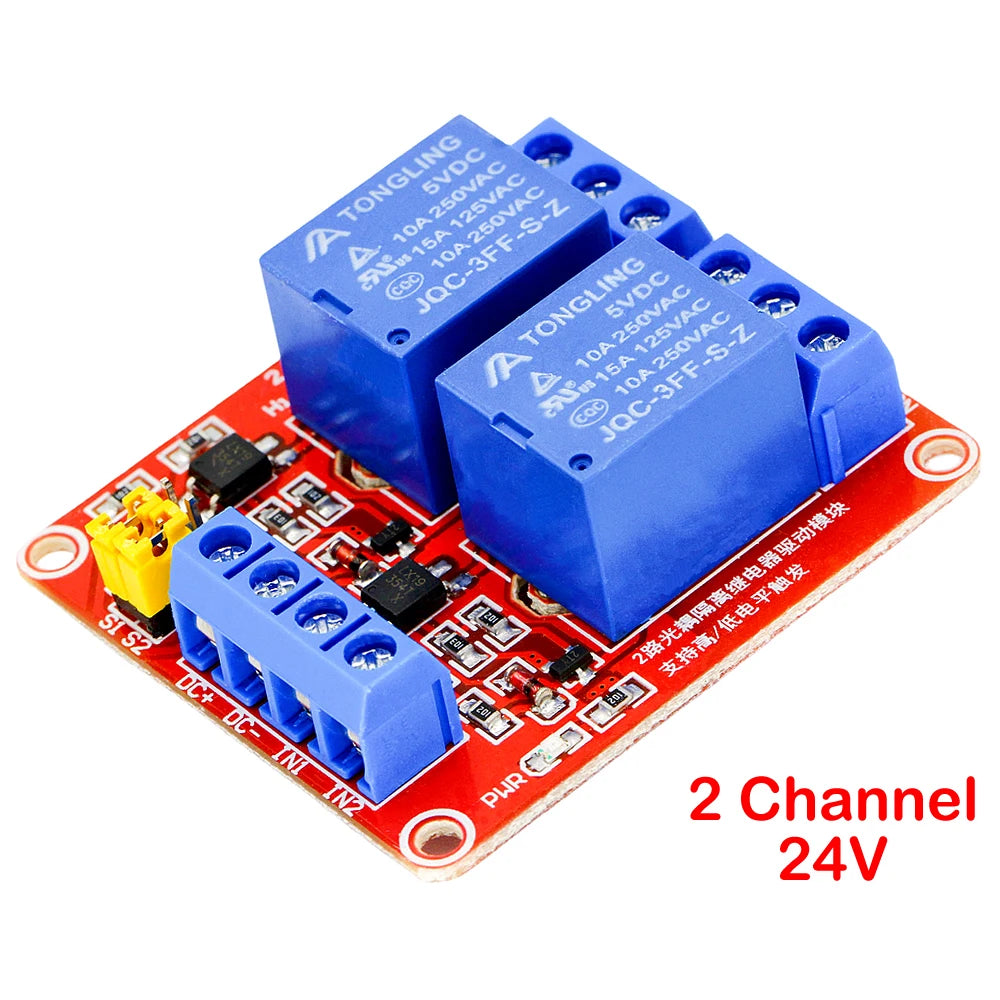
2-Channel Relay Module — 5V / 12V / 24V | Optocoupler Isolated | AC 250V 10A | High/Low Level Trigger
A versatile, optocoupler-isolated 2-channel relay module that lets any microcontroller — Arduino, ESP32, Raspberry Pi, or STM32 — switch mains AC loads (up to 250V/10A) and DC loads (up to 30V/10A) safely and reliably. The critical feature of this module is its optocoupler isolation: the control circuit (your microcontroller) is electrically separated from the relay coil and load circuit, protecting your microcontroller from voltage spikes, inductive kickback, and ground loops that would otherwise damage or reset it. A jumper wire selects high-level or low-level trigger to match your microcontroller’s output logic. Available in 5V, 12V, and 24V coil voltage versions.
Specifications
| Channels | 2 (independent) |
| Coil Voltage | 5V DC / 12V DC / 24V DC (as selected) |
| Trigger Current | 5mA |
| Trigger Level | High or Low (jumper selectable) |
| Isolation | Optocoupler (electrical isolation between control and load) |
| Max AC Load | AC 250V / 10A |
| Max DC Load | DC 30V / 10A |
| Module Dimensions | 50 × 41 × 18.5mm |
| Indicators | Green (power) + Red per channel (relay status) |
| Output Terminals | NC, COM, NO per channel (6 screw terminals total) |
Why Optocoupler Isolation Matters
Relay coils are inductive loads — when switched off, they generate a voltage spike (back-EMF) that can be many times the supply voltage. Without isolation, this spike travels back through the control signal line and into your microcontroller’s GPIO pin, causing:
- GPIO pin damage — overvoltage destroys the input protection diodes on the microcontroller pin
- Microcontroller reset — voltage spikes on the power rail cause brownout resets
- Data corruption — electrical noise from relay switching corrupts I2C, SPI, and UART communications
- Ground loops — shared ground between high-current relay circuits and sensitive microcontroller circuits causes measurement errors
The optocoupler on this module uses an LED and phototransistor to transmit the control signal as light — completely breaking the electrical connection between the microcontroller and the relay coil. Your microcontroller is fully protected.
High vs. Low Level Trigger — How to Choose
| Trigger Mode | Relay ON when | Relay OFF when | Use with |
|---|---|---|---|
| High Level | Signal = HIGH (3.3V or 5V) | Signal = LOW (0V) | Most Arduino/ESP32 GPIO outputs |
| Low Level | Signal = LOW (0V) | Signal = HIGH (3.3V or 5V) | Open-collector outputs, active-low systems |
Set the trigger level using the jumper wire on the module. No code changes required — just move the jumper.
Output Terminal Wiring
| Terminal | Function | Connect To |
|---|---|---|
| COM | Common (always connected) | One side of your load or power supply |
| NO | Normally Open (open when relay OFF) | Load — circuit closes when relay activates |
| NC | Normally Closed (closed when relay OFF) | Load — circuit opens when relay activates |
Key Features
- ✅ Optocoupler isolation — full electrical separation between microcontroller and relay/load circuit
- ✅ AC 250V / 10A load rating — switches mains lighting, motors, heaters, and appliances
- ✅ DC 30V / 10A load rating — switches DC motors, solenoids, and high-current DC loads
- ✅ High/Low trigger selectable — jumper wire selects trigger polarity, no code changes needed
- ✅ 5mA trigger current — compatible with 3.3V and 5V GPIO outputs from Arduino, ESP32, Raspberry Pi
- ✅ LED status indicators — green power LED + red relay status LED per channel for visual feedback
- ✅ NC/COM/NO terminals — both normally-open and normally-closed configurations available per channel
- ✅ Compact 50×41×18.5mm — fits in standard project enclosures
Common Applications
- Arduino home automation — switching lights, fans, and appliances
- ESP32 / ESP8266 WiFi-controlled mains switching
- Raspberry Pi GPIO relay control for home automation
- Industrial PLC output expansion
- Greenhouse and aquarium automation (lights, pumps, heaters)
- 3D printer heated bed and hotend power switching
- CNC machine spindle and coolant pump control
- Automatic irrigation system pump control
Arduino Wiring Example
- Connect module VCC to Arduino 5V (or 12V/24V external supply for 12V/24V versions).
- Connect module GND to Arduino GND.
- Connect IN1 to Arduino digital pin (e.g., D7) for channel 1 control.
- Connect IN2 to Arduino digital pin (e.g., D8) for channel 2 control.
- Set jumper to HIGH trigger (default for most Arduino projects).
- Wire your AC or DC load between COM and NO (or NC) terminals.
- Use
digitalWrite(7, HIGH)to activate relay 1,digitalWrite(7, LOW)to deactivate.
Warning: AC mains wiring must be performed by a qualified electrician. Ensure all mains connections are insulated and the module is housed in a suitable enclosure before powering.
Frequently Asked Questions
Q: Can I use the 5V module with a 3.3V Arduino (e.g., Arduino Due, ESP32)?
A: Yes. The optocoupler trigger current is only 5mA, which is within the output capability of 3.3V GPIO pins. The relay coil is powered separately from the module VCC — connect VCC to 5V and use 3.3V signals on the IN pins.
Q: Can I switch both channels simultaneously?
A: Yes. Both channels are independent and can be activated simultaneously or in any sequence.
Q: What is the relay switching lifetime?
A: Standard relay modules of this type are rated for approximately 100,000 mechanical switching cycles at rated load. Reduce load current to extend relay life.
Package Contents
- 1× 2-Channel Relay Module (coil voltage as selected: 5V / 12V / 24V)


- ★Product Description
- ★About us
- ★Custom cable
2-Channel Relay Module — 5V / 12V / 24V | Optocoupler Isolated | AC 250V 10A | High/Low Level Trigger
A versatile, optocoupler-isolated 2-channel relay module that lets any microcontroller — Arduino, ESP32, Raspberry Pi, or STM32 — switch mains AC loads (up to 250V/10A) and DC loads (up to 30V/10A) safely and reliably. The critical feature of this module is its optocoupler isolation: the control circuit (your microcontroller) is electrically separated from the relay coil and load circuit, protecting your microcontroller from voltage spikes, inductive kickback, and ground loops that would otherwise damage or reset it. A jumper wire selects high-level or low-level trigger to match your microcontroller’s output logic. Available in 5V, 12V, and 24V coil voltage versions.
Specifications
| Channels | 2 (independent) |
| Coil Voltage | 5V DC / 12V DC / 24V DC (as selected) |
| Trigger Current | 5mA |
| Trigger Level | High or Low (jumper selectable) |
| Isolation | Optocoupler (electrical isolation between control and load) |
| Max AC Load | AC 250V / 10A |
| Max DC Load | DC 30V / 10A |
| Module Dimensions | 50 × 41 × 18.5mm |
| Indicators | Green (power) + Red per channel (relay status) |
| Output Terminals | NC, COM, NO per channel (6 screw terminals total) |
Why Optocoupler Isolation Matters
Relay coils are inductive loads — when switched off, they generate a voltage spike (back-EMF) that can be many times the supply voltage. Without isolation, this spike travels back through the control signal line and into your microcontroller’s GPIO pin, causing:
- GPIO pin damage — overvoltage destroys the input protection diodes on the microcontroller pin
- Microcontroller reset — voltage spikes on the power rail cause brownout resets
- Data corruption — electrical noise from relay switching corrupts I2C, SPI, and UART communications
- Ground loops — shared ground between high-current relay circuits and sensitive microcontroller circuits causes measurement errors
The optocoupler on this module uses an LED and phototransistor to transmit the control signal as light — completely breaking the electrical connection between the microcontroller and the relay coil. Your microcontroller is fully protected.
High vs. Low Level Trigger — How to Choose
| Trigger Mode | Relay ON when | Relay OFF when | Use with |
|---|---|---|---|
| High Level | Signal = HIGH (3.3V or 5V) | Signal = LOW (0V) | Most Arduino/ESP32 GPIO outputs |
| Low Level | Signal = LOW (0V) | Signal = HIGH (3.3V or 5V) | Open-collector outputs, active-low systems |
Set the trigger level using the jumper wire on the module. No code changes required — just move the jumper.
Output Terminal Wiring
| Terminal | Function | Connect To |
|---|---|---|
| COM | Common (always connected) | One side of your load or power supply |
| NO | Normally Open (open when relay OFF) | Load — circuit closes when relay activates |
| NC | Normally Closed (closed when relay OFF) | Load — circuit opens when relay activates |
Key Features
- ✅ Optocoupler isolation — full electrical separation between microcontroller and relay/load circuit
- ✅ AC 250V / 10A load rating — switches mains lighting, motors, heaters, and appliances
- ✅ DC 30V / 10A load rating — switches DC motors, solenoids, and high-current DC loads
- ✅ High/Low trigger selectable — jumper wire selects trigger polarity, no code changes needed
- ✅ 5mA trigger current — compatible with 3.3V and 5V GPIO outputs from Arduino, ESP32, Raspberry Pi
- ✅ LED status indicators — green power LED + red relay status LED per channel for visual feedback
- ✅ NC/COM/NO terminals — both normally-open and normally-closed configurations available per channel
- ✅ Compact 50×41×18.5mm — fits in standard project enclosures
Common Applications
- Arduino home automation — switching lights, fans, and appliances
- ESP32 / ESP8266 WiFi-controlled mains switching
- Raspberry Pi GPIO relay control for home automation
- Industrial PLC output expansion
- Greenhouse and aquarium automation (lights, pumps, heaters)
- 3D printer heated bed and hotend power switching
- CNC machine spindle and coolant pump control
- Automatic irrigation system pump control
Arduino Wiring Example
- Connect module VCC to Arduino 5V (or 12V/24V external supply for 12V/24V versions).
- Connect module GND to Arduino GND.
- Connect IN1 to Arduino digital pin (e.g., D7) for channel 1 control.
- Connect IN2 to Arduino digital pin (e.g., D8) for channel 2 control.
- Set jumper to HIGH trigger (default for most Arduino projects).
- Wire your AC or DC load between COM and NO (or NC) terminals.
- Use
digitalWrite(7, HIGH)to activate relay 1,digitalWrite(7, LOW)to deactivate.
Warning: AC mains wiring must be performed by a qualified electrician. Ensure all mains connections are insulated and the module is housed in a suitable enclosure before powering.
Frequently Asked Questions
Q: Can I use the 5V module with a 3.3V Arduino (e.g., Arduino Due, ESP32)?
A: Yes. The optocoupler trigger current is only 5mA, which is within the output capability of 3.3V GPIO pins. The relay coil is powered separately from the module VCC — connect VCC to 5V and use 3.3V signals on the IN pins.
Q: Can I switch both channels simultaneously?
A: Yes. Both channels are independent and can be activated simultaneously or in any sequence.
Q: What is the relay switching lifetime?
A: Standard relay modules of this type are rated for approximately 100,000 mechanical switching cycles at rated load. Reduce load current to extend relay life.
Package Contents
- 1× 2-Channel Relay Module (coil voltage as selected: 5V / 12V / 24V)


- ♥Hear From Our Happy Customers
- ♥Verified Buyer Reviews
- ♥Trusted by Professionals and Engineers