- ★Product Description
- ★About us
- ★Custom cable
DESCRIPTION
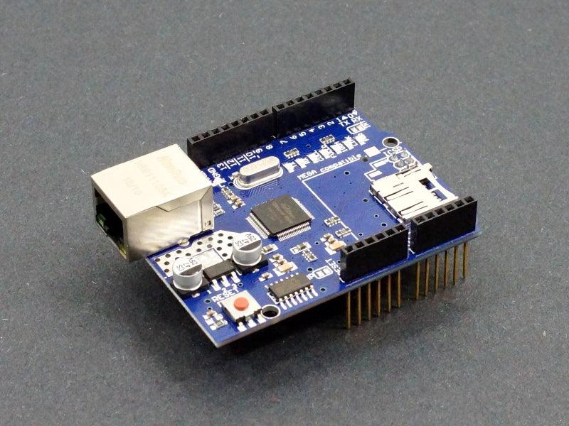
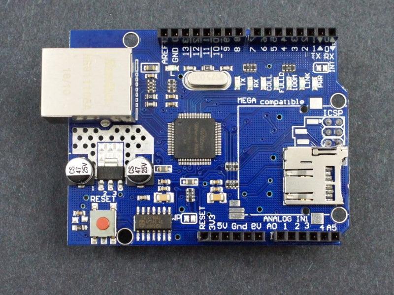
This shield allows an Arduino to establish a wired Ethernet connection to a network and is compatible with Uno, Mega and boards with compatible I/O pins.
PACKAGE INCLUDES:
- Ethernet Shield W5100
KEY FEATURES OF ETHERNET SHIELD W5100:
- WIZnet W5100 Ethernet controller
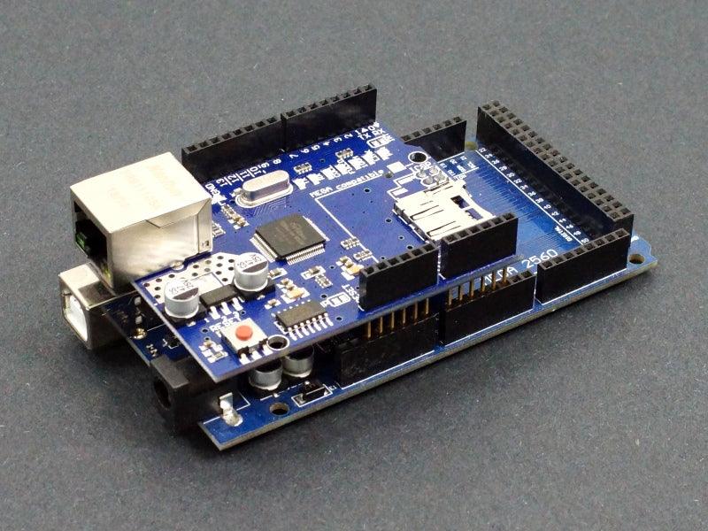
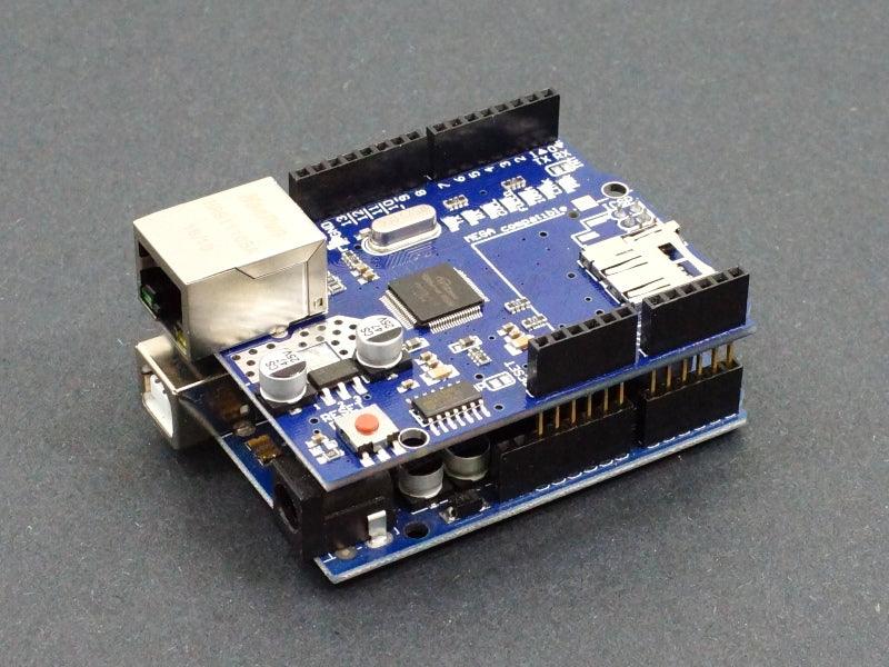
- Compatible with both Uno and Mega footprints
- Standard RJ-45 CAT network connector
- Auto MDI/MDIX (auto cable pin swap)
- Acts as client or server
- TCP/IP protocols include TCP, UDP, ICMP, IPv4 ARP, IGMP, Ethernet
- 10BaseT/100BaseTX Ethernet PHY embedded
- Up to 4 simultaneous socket connections
- MicroSD card slot
- SPI Interface
- 5V compatible, operates at 3.3V internally
- Good library support
This Ethernet shield uses the WIZnet W5100 network interface chip to provide a cabled connection to a network. The board also has an SD Micro card slot for data storage. The board does not support wireless Ethernet.
The W5100 is an older chip, but has very good library support and tends to be the go-to for wired Ethernet for Arduino and compatibles. The shield is compatible with both the Uno and Mega style footprints and uses the SPI interface which is picked up from the ICSP header.
SPI Interface
Arduino and compatibles communicate with both the W5100 chip and SD card slot using the SPI bus.
MOSI / MISO and SCK are picked up off the ICSP header, but are also found on digital pins 11, 12 and 13 on the Uno and pins 50, 51 and 52 on the Mega. On both boards, pin 10 is used to select the W5100 chip and pin 4 is used for the SD card slot. These pins cannot be used for general purpose I/O.
On the Mega, the hardware SS pin 53 is not used, but it must be kept as an output or the SPI interface will not work.
Note that because the W5100 and SD card share the SPI bus, only one can be active at a time. If you are using both peripherals in your program this should be taken care of by the corresponding libraries. If you are not using one of the peripherals in your program, you will want to explicitly deselect it. To do this with the SD card, either remove any SD card or set pin 4 as an output and write a high to it. For the W5100, you can set the digital pin 10 as an output and write a high to it to disable it.
LED Indicators
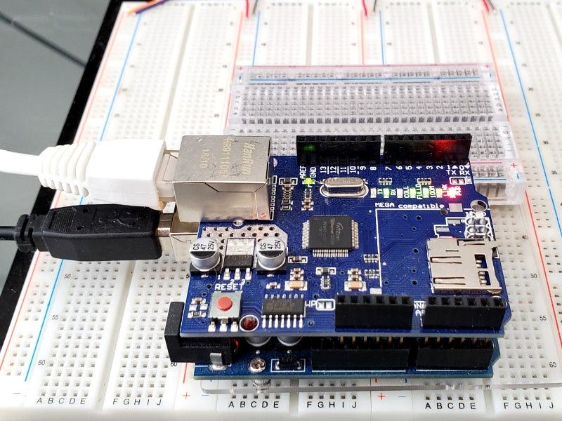
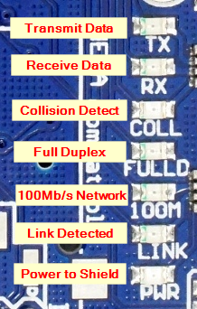
The shield provides a number of informational LEDs that can be useful for troubleshooting the network connection:
Ethernet Shield W5100 – LEDs
- PWR = Indicates that the shield is being powered by the Uno or Mega.
- LINK = Indicates the presence of a network link and flashes when the shield transmits or receives data.
- FULLD = Indicates that the network connection is full duplex.
- 100M = Indicates the presence of a 100Mb/s network connection (as opposed to 10Mb/s)
- RX = Flashes when the shield receives data
- TX = Flashes when the shield sends data
- COLL = Flashes when network collisions are detected
Arduino to Shield Pin Connections
All of the I/O is brought up to stackable female headers on the shield except for the IOREF and the two I2C pins hear the USB connector so it can support a daughter shield as long as it does not conflict with the pins in use.
The shield uses the following pins
- Uno SPI = D11, D12, D13
- Mega SPI = D50, D51, D52
- W5100 Enable = D10
- SD Card Enable = D4
The board includes a solder jumper location labeled INT. If it is bridged, it allows the Arduino to receive interrupt-driven notification of events from the W5100, but this functionality is not supported by the Ethernet library. The jumper connects the INT pin of the W5100 to D2 of the Arduino.
OUR EVALUATION RESULTS:
These shields work quite well for establishing robust wired Ethernet connections but there is an issue to be aware of if you purchased your board somewhere else.
511 Resistor Issue
Ethernet Shield W5100 – 510 Resistor
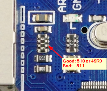
There are some boards on the market which are built with the wrong resistor pack and will not work correctly. We inspect for this issue, but if you bought your board somewhere else, you will want to verify that you have the correct part on your board or you will get intermittent or no operation.
The resistor pack in question is located just behind the RJ-45 connector. The specified part is 49.9 ohm which is labeled as 49R9. These parts are hard to get, so boards are typically built with 51 ohm parts that work just as well and they are labeled 510. Some boards are built with parts labeled 511 which is 510 ohms and these do not work reliabilty.
Testing Your Ethernet Shield W5100 Board
The test program here is based on the Webserver example that comes with the Arduino IDE. It sets up the shield as a webserver, takes the readings of analog inputs A0 – A5 and sends the readings to a window open in your web browser. If there is nothing attached to those inputs, you will see floating values. You can easily attach a pot or something to one of the analog inputs if you want to twiddle something and show the value change in the web browser.
Steps to setup
- Insert the Ethernet Shield onto the Uno or Mega board. The header pins are quite long and flexible. You may need to coax them into alignment as you insert the shield into the Arduino board.
- Connect USB from PC to the Arduino.
- Connect a network CAT cable from the RJ-45 jack to a router. You should see some of the LEDs on the board and connector light to show that a link is detected.
- Download the program
- Open a browser window and point it to the Arduino which is now acting as a webserver. In our example here, we type 10.0.0.12 in the
Finding PC IP AddressThe MAC address used can typically be arbitrary and the one in the program will work. Some boards may have a label on it with a specific MAC address listed and that should be used instead.
The IP address used needs to match the address range of your network.
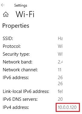
To find that information, open the network settings / properties window for your PC. In our example we are using a wireless connection and need to open our wireless network properties window.
You will find a item IPv4 address: which is the IP address of your computer on your local network. In our example to the right the IP address is 10.0.0.120
You will want to set the shield address to match the same first 3 numbers (10.0.0) in our example. The 4th number can be set to anything but needs to be unique on your network.
Open a browser window and point it to the shield address which is 10.0.0.12 in our example.
Once you get everything up and running, you should see something similar to this in your browser window.
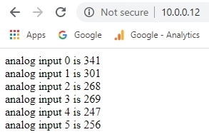
Webserver Example output
Ethernet Shield W5100 Test Program
/*
  Ethernet Shield Test

 A simple test program based on the Webserver demo

 Setup:
 * Plug Ethernet Shield onto Uno or Mega 2560
 * Connect USB to Arduino
 * Connect Ethernet cable from Ethernet shield to router
 * Analog inputs attached to pins A0 through A5 (optional)
 * Update IP address below if needed to match network
 * Download software
 * Open Serial Monitor window
 * Open browser window and point to IP address: 10.0.0.12 in this example
 */

#include <SPI.h>
#include <Ethernet.h>

// Enter a MAC address.  Can usually be arbitrary
byte mac[] = {
  0xDE, 0xAD, 0xBE, 0xEF, 0xFE, 0xED
};

// The IP address will be dependent on your local network
// First 3 numbers must match router, last must be unique
IPAddress ip(10, 0, 0, 12);

// Initialize the Ethernet server library with the IP address and port
// to use.  (port 80 is default for HTTP):
EthernetServer server(80);
//===============================================================================
//  Initialization
//===============================================================================
void setup() {
  Serial.begin(9600);
  Serial.println("Ethernet Shield Test");

  // start the Ethernet connection and the server:
  Ethernet.begin(mac, ip);

  // Check for Ethernet hardware present
  if (Ethernet.hardwareStatus() == EthernetNoHardware) {
    Serial.println("Ethernet shield was not found - Stopping Test");
    while (true) {
      delay(1); // do nothing, no point running without Ethernet hardware
    }
  }

  // start the server
  server.begin();
  Serial.print("server is at ");
  Serial.println(Ethernet.localIP());
}
//===============================================================================
//  Main
//===============================================================================
void loop() {
  // listen for incoming clients
  EthernetClient client = server.available();
  if (client) {
    Serial.println("new client");
    // an http request ends with a blank line
    boolean currentLineIsBlank = true;
    while (client.connected()) {
      if (client.available()) {
        char c = client.read();
        Serial.write(c);
        // if you've gotten to the end of the line (received a newline
        // character) and the line is blank, the http request has ended,
        // so you can send a reply
        if (c == '\n' && currentLineIsBlank) {
          // send a standard http response header
          client.println("HTTP/1.1 200 OK");
          client.println("Content-Type: text/html");
          client.println("Connection: close");  // the connection will be closed after completion of the response
          client.println("Refresh: 5");  // refresh the page automatically every 5 sec
          client.println();
          client.println("<!DOCTYPE HTML>");
          client.println("<html>");
          // output the value of each analog input pin
          for (int analogChannel = 0; analogChannel < 6; analogChannel++) {
            int sensorReading = analogRead(analogChannel);
            client.print("analog input ");
            client.print(analogChannel);
            client.print(" is ");
            client.print(sensorReading);
            client.println("<br />");
          }
          client.println("</html>");
          break;
        }
        if (c == '\n') {
          // you're starting a new line
          currentLineIsBlank = true;
        } else if (c != '\r') {
          // you've gotten a character on the current line
          currentLineIsBlank = false;
        }
      }
    }
    // give the web browser time to receive the data
    delay(1);
    // close the connection:
    client.stop();
    Serial.println("client disconnected");
  }
}
BEFORE THEY ARE SHIPPED, THESE MODULES ARE:
- Inspected
- Resistor pack verified
- Installed on Uno or Mega and tested with the test program.
- Repackaged in quality recloseable ESD bags for safe storage.
Notes:
- None
TECHNICAL SPECIFICATIONS
| Dimensions | ||
| PCB Board (L x W) | 68 x 53 mm (2.68 x 2.09″) | |
| Country of Origin | China | |
| Datasheet | WIZnet | WIZnet W5100 |
FURTHER READING


