
Keszoox
PC817 / EL817 Optocoupler DIP-4 Phototransistor Output 5kV Isolation (5-Pack)
PC817 / EL817 Optocoupler DIP-4 Phototransistor Output 5kV Isolation (5-Pack)

Couldn't load pickup availability
PC817 / EL817 Optocoupler — DIP-4, 5kV Isolation, Phototransistor Output (5-Pack)
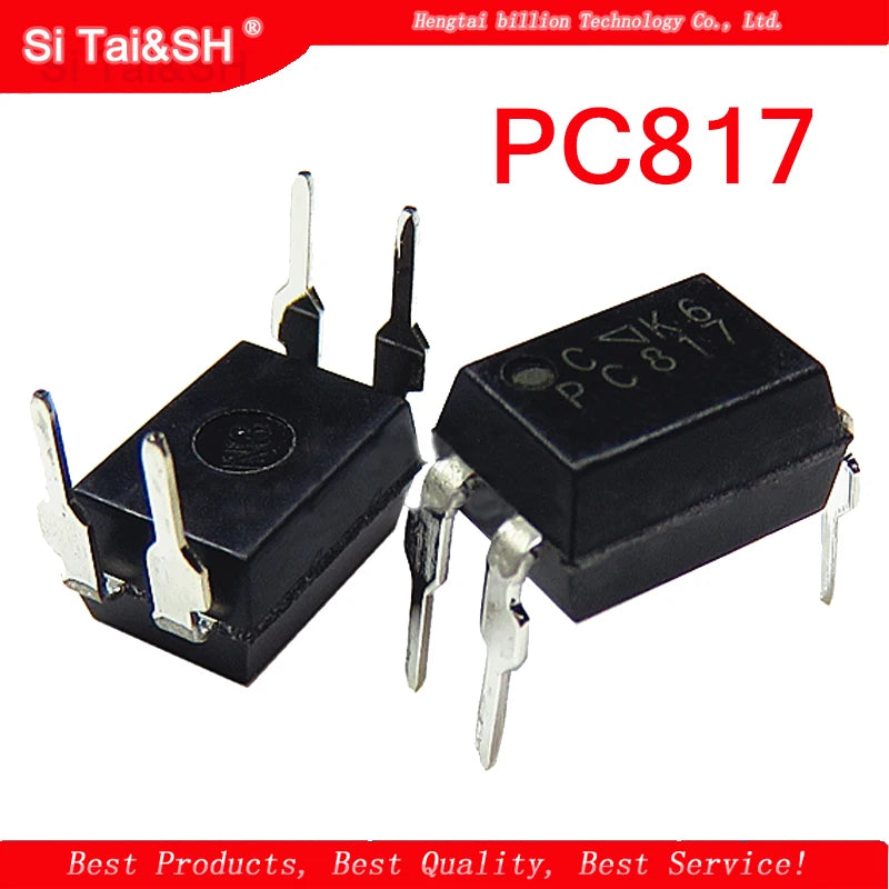
The PC817 (also sold as EL817, FL817C, PS817C) is the world’s most widely used general-purpose optocoupler in a DIP-4 through-hole package. It provides 5kV AC isolation between input (LED) and output (phototransistor), making it essential for MCU-to-relay isolation, SMPS feedback loops, and any circuit requiring galvanic separation between control and power sections.
Key Specifications
| Parameter | Value |
|---|---|
| Part Number | PC817 / EL817 / FL817C / PS817C |
| Package | DIP-4 |
| Isolation Voltage | 5,000V AC (1 minute) |
| CTR (Current Transfer Ratio) | 50–300% @ IF=5mA (Grade C: 100–300%) |
| Input LED Forward Voltage | 1.2V typical @ IF=20mA |
| Input LED Current (IF max) | 50mA |
| Output Transistor VCEO | 80V |
| Output Transistor IC max | 50mA |
| Response Time (rise/fall) | ~4μs / ~3μs |
| Operating Temperature | −30°C to +100°C |
| Quantity | 5 pieces |
PC817 Grade Selection
| Grade | CTR Range | Marking |
|---|---|---|
| A | 50–100% | PC817A |
| B | 100–200% | PC817B |
| C | 200–300% | PC817C |
| D | 300–600% | PC817D |
Why Choose PC817?
- 5kV Isolation — Meets IEC 60950 and UL safety requirements for mains-isolated circuits
- Universal Replacement — PC817, EL817, FL817C, PS817C are all electrically identical and pin-compatible
- 80V Output Transistor — Suitable for relay drive, optoisolated gate drive, and signal isolation
- DIP-4 Package — Breadboard-friendly, easy to prototype and replace
- Industry Standard — Used in virtually every SMPS, inverter, and industrial control board
Typical Applications
- MCU-to-relay galvanic isolation (Arduino controlling 230V relay)
- SMPS optoisolated feedback loop (flyback converter output regulation)
- RS-232/RS-485 signal isolation
- AC zero-crossing detection circuit
- Isolated gate drive for TRIAC and SCR
- Industrial PLC I/O isolation
Typical Circuit (MCU to Relay)
MCU GPIO → 330Ω resistor → PC817 LED anode (pin 1). LED cathode (pin 2) → GND. Phototransistor collector (pin 4) → relay coil + pull-up to VCC. Emitter (pin 3) → GND.
FAQ
Q: What resistor value for PC817 LED with 5V MCU GPIO?
A: R = (5V − 1.2V) / 10mA = 380Ω. Use 390Ω standard value. For 3.3V: R = (3.3V − 1.2V) / 10mA = 210Ω, use 220Ω.
Q: Can PC817 switch AC signals?
A: No — the output phototransistor is a DC device. For AC switching isolation, use a TRIAC optocoupler (MOC3021, MOC3041).
Package Contents
- 5× PC817 / EL817 DIP-4 Optocoupler