


NDP6020P P-Channel Power MOSFET — 20V / 24A, TO-220, Logic-Level, High-Side Switch
NDP6020P P-Channel Power MOSFET 20V / 24A, TO-220, Logic-Level, High-Side Switch
Compatible JST cables for sensors and modules — secure & reliable. Shop now.

Couldn't load pickup availability
NDP6020P P-Channel Power MOSFET — 20V / 24A, TO-220, Logic-Level
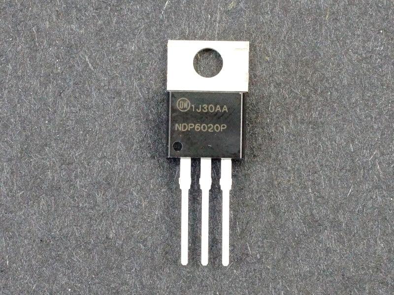
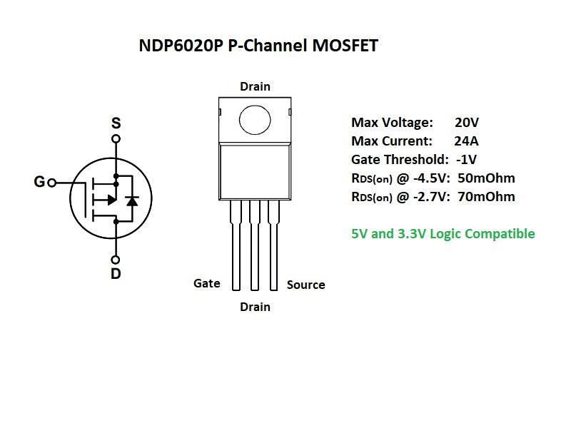
The NDP6020P is a logic-level P-channel power MOSFET rated at -20V / -24A with an on-resistance of 45mΩ @ Vgs=-10V. P-channel MOSFETs are the natural choice for high-side switching — where the load sits between the MOSFET and ground — because they turn on when the gate is pulled LOW relative to the source, eliminating the need for a bootstrap gate driver circuit required by high-side N-channel configurations. The logic-level gate threshold allows direct drive from a 5V microcontroller in 12V high-side switch applications.
Key Specifications
| Parameter | Value |
|---|---|
| Channel Type | P-Channel |
| Drain-Source Voltage (Vds) | -20V |
| Continuous Drain Current (Id) | -24A @ Tc=25°C |
| Pulsed Drain Current (Idm) | -96A |
| On-Resistance (Rds(on)) | 45mΩ @ Vgs=-10V |
| Gate Threshold Voltage (Vgs(th)) | -1.0V to -2.5V |
| Logic-Level Gate Drive | Fully on @ Vgs=-4.5V |
| Total Power Dissipation | 50W @ Tc=25°C |
| Package | TO-220 (through-hole) |
| Operating Temperature | -55°C to +175°C |
| Manufacturer | ON Semiconductor (onsemi) |
| RoHS Compliant | Yes |
P-Channel vs N-Channel — When to Use Each
| Configuration | N-Channel | P-Channel (NDP6020P) |
|---|---|---|
| Switch Position | Low-side (between load and GND) | High-side (between supply and load) |
| Gate Drive (turn ON) | Pull gate HIGH above source | Pull gate LOW below source |
| High-Side Drive Complexity | Requires bootstrap driver | ✅ Simple — pull gate to GND to turn on |
| Rds(on) (same die size) | Lower (2–3× better) | Higher |
| Best For | Low-side, H-bridge, DC-DC | High-side load switch, reverse protection |
Why Choose the NDP6020P?
- Simple high-side switching — connect source to 12V supply, drain to load; pull gate LOW to turn on — no bootstrap driver needed
- Logic-level gate — a 5V Arduino can drive the gate via an NPN transistor or N-channel MOSFET level shifter for clean switching
- Reverse polarity protection — P-channel MOSFETs are commonly used as ideal diodes for reverse polarity protection with near-zero voltage drop
- 24A continuous current — handles high-current 12V loads including motors, LED strips, and solenoids
Typical Applications
- High-side load switch for 12V systems (Arduino-controlled power switching)
- Reverse polarity protection (ideal diode replacement)
- P-channel high-side switch in H-bridge motor driver
- Battery charger power path management
- Automotive 12V accessory high-side switching
- Power sequencing and OR-ing circuits
Frequently Asked Questions
Q: How do I drive a P-channel MOSFET from a 5V Arduino for a 12V load?
Connect the source to 12V and the load between drain and GND. To turn ON: use an NPN transistor (e.g. 2N2222) or N-channel MOSFET with its collector/drain connected to the P-MOSFET gate via a pull-up resistor to 12V. When the Arduino drives the NPN base HIGH, it pulls the P-MOSFET gate LOW (to ~0V), turning it on. A gate resistor of 100–470Ω limits gate current spikes.
Q: Why is P-channel Rds(on) higher than N-channel?
P-channel MOSFETs use holes as charge carriers, which have lower mobility than electrons (used in N-channel). This means a P-channel die must be larger to achieve the same Rds(on), resulting in higher on-resistance for the same package size. For high-efficiency designs requiring low Rds(on), use an N-channel MOSFET with a bootstrap gate driver on the high side.
Package Contents
- 1× NDP6020P P-Channel Power MOSFET (TO-220)

- ★Product Description
- ★About us
- ★Custom cable
NDP6020P P-Channel Power MOSFET — 20V / 24A, TO-220, Logic-Level
The NDP6020P is a logic-level P-channel power MOSFET rated at -20V / -24A with an on-resistance of 45mΩ @ Vgs=-10V. P-channel MOSFETs are the natural choice for high-side switching — where the load sits between the MOSFET and ground — because they turn on when the gate is pulled LOW relative to the source, eliminating the need for a bootstrap gate driver circuit required by high-side N-channel configurations. The logic-level gate threshold allows direct drive from a 5V microcontroller in 12V high-side switch applications.
Key Specifications
| Parameter | Value |
|---|---|
| Channel Type | P-Channel |
| Drain-Source Voltage (Vds) | -20V |
| Continuous Drain Current (Id) | -24A @ Tc=25°C |
| Pulsed Drain Current (Idm) | -96A |
| On-Resistance (Rds(on)) | 45mΩ @ Vgs=-10V |
| Gate Threshold Voltage (Vgs(th)) | -1.0V to -2.5V |
| Logic-Level Gate Drive | Fully on @ Vgs=-4.5V |
| Total Power Dissipation | 50W @ Tc=25°C |
| Package | TO-220 (through-hole) |
| Operating Temperature | -55°C to +175°C |
| Manufacturer | ON Semiconductor (onsemi) |
| RoHS Compliant | Yes |
P-Channel vs N-Channel — When to Use Each
| Configuration | N-Channel | P-Channel (NDP6020P) |
|---|---|---|
| Switch Position | Low-side (between load and GND) | High-side (between supply and load) |
| Gate Drive (turn ON) | Pull gate HIGH above source | Pull gate LOW below source |
| High-Side Drive Complexity | Requires bootstrap driver | ✅ Simple — pull gate to GND to turn on |
| Rds(on) (same die size) | Lower (2–3× better) | Higher |
| Best For | Low-side, H-bridge, DC-DC | High-side load switch, reverse protection |
Why Choose the NDP6020P?
- Simple high-side switching — connect source to 12V supply, drain to load; pull gate LOW to turn on — no bootstrap driver needed
- Logic-level gate — a 5V Arduino can drive the gate via an NPN transistor or N-channel MOSFET level shifter for clean switching
- Reverse polarity protection — P-channel MOSFETs are commonly used as ideal diodes for reverse polarity protection with near-zero voltage drop
- 24A continuous current — handles high-current 12V loads including motors, LED strips, and solenoids
Typical Applications
- High-side load switch for 12V systems (Arduino-controlled power switching)
- Reverse polarity protection (ideal diode replacement)
- P-channel high-side switch in H-bridge motor driver
- Battery charger power path management
- Automotive 12V accessory high-side switching
- Power sequencing and OR-ing circuits
Frequently Asked Questions
Q: How do I drive a P-channel MOSFET from a 5V Arduino for a 12V load?
Connect the source to 12V and the load between drain and GND. To turn ON: use an NPN transistor (e.g. 2N2222) or N-channel MOSFET with its collector/drain connected to the P-MOSFET gate via a pull-up resistor to 12V. When the Arduino drives the NPN base HIGH, it pulls the P-MOSFET gate LOW (to ~0V), turning it on. A gate resistor of 100–470Ω limits gate current spikes.
Q: Why is P-channel Rds(on) higher than N-channel?
P-channel MOSFETs use holes as charge carriers, which have lower mobility than electrons (used in N-channel). This means a P-channel die must be larger to achieve the same Rds(on), resulting in higher on-resistance for the same package size. For high-efficiency designs requiring low Rds(on), use an N-channel MOSFET with a bootstrap gate driver on the high side.
Package Contents
- 1× NDP6020P P-Channel Power MOSFET (TO-220)


