
The most practical tips for solderless breadboard
This solderless breadboard guide provides information on how they are constructed and used and how to select the best one for your requirements.
If you are shopping for a solderless breadboard here on our Keszoox.com site or elsewhere, you may be wondering why two basically identical looking solderless breadboards have significantly different prices. That leads to wondering what you are getting for your extra money if you pony up for the more expensive version or if you would be OK if you just get the cheaper one. Since good information on solderless breadboards can be hard to come by, we have created this guide to help.
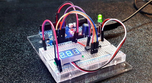
Solderless breadboards have been around for a long time and are designed to be used with components that have leads such as DIP style ICs and leaded resistors and capacitors.
In many ways they seem old school in today’s world where most components are going Surface Mount Technology (SMT). While SMT components are better in almost every other way compared to leaded parts, there is no easy way to directly prototype with these newer SMT devices without designing a PCB to mount them. For that reason and for the foreseeable future many of the new and more interesting SMT devices will continue to be adapted for use with solderless breadboards by mounting them on breakout boards of some type so that hobbyists don’t need to design and fabricate a PCB every time they want to work with a circuit.
For the sake of brevity, we will refer to solderless breadboards as just breadboards for the rest of this article. The term breadboard is also sometimes use for prototype PCBs or perf boards which are designed to prototype a circuit by soldering the components in place and making connections using wires. When we use the term ‘breadboard’ here we are referring only to solderless breadboards.
Contents
- Breadboard Basics
- Breadboard Pros & Cons
- Breadboard Quality and Features to Consider
- Spring Contacts
- Power Rails
- Plastic Housing
- Breadboard to Breadboard Physical Mating
- Breadboard Backing
- Breadboard Assemblies
- Size and Quantity of Breadboards to Buy
- Supplying Power to the Breadboard
Breadboard Basics
For anyone new to breadboards, they are simple yet clever devices so a quick introduction is probably in order.
The breadboard consists of a plastic housing usually made of ABS plastic that has a series of holes arranged in rows of 5. These holes are sized to allow wire of up to 20 AWG to be inserted. Each of the rows of 5 holes has internal spring contacts that connect the 5 holes electrically. These contacts are inserted into the plastic housing from the back side. When a component lead or wire is inserted into one of these holes, the spring contacts electrically connect it to anything else that is inserted into one of the other 4 remaining holes in the same row of contacts. This forms a circuit node.
These rows of contacts are then arranged into two columns. These two columns of contacts are separated by a 0.3” space to form a breadboard. This spacing is chosen because the typical DIP style IC has leads on a 0.3” spacing from one side of the IC to the other. By placing the IC across this space in the middle of the breadboard, each of the pins of the IC is connected to its own separate row of 5 contacts.
The holes of the breadboard are spaced 0.1” (2.54mm) apart in both the X and Y direction which is the spacing used for adjacent DIP IC leads as well as many other components such as headers. When using multi-leaded components with a breadboard, the leads need to be on 0.1” centers or a multiple of that dimension to fit the grid pattern. In some cases, if the leads are fairly long such as with resistors and capacitors, they can be formed to fit that spacing pattern.
These plastic housings are made in several standard lengths to create the basic breadboard. Most breadboards then have columns of vertically connected contacts added on the sides. These vertical contacts create power and ground rails that extend the length of the breadboard. Power or ground can then be jumpered to one of these locations from a power source and then be available along the entire length of the breadboard so that it can easily be jumped to any circuit nodes where it is needed.
Each of the electrical connection points (or nodes) is referred to as a ‘tie-point’, so you will often find breadboards listed as an 830 tie-point breadboard as an example which would indicate that it has a total of 830 electrical connection points including any that are included in the power rails. The picture below shows a 400 tie-point breadboard.

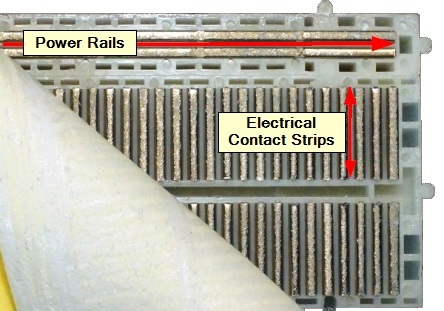
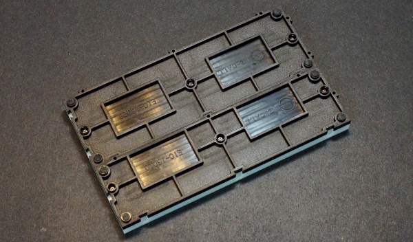
The contacts which are inserted from the back of the plastic housing are usually held in place with a double-sided tape. It is peeled back in the picture below to show the contacts from the backside of the breadboard.
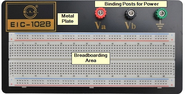
It can then be taken one step further with one or several of these individual breadboards mounted to a metal plate which keeps the breadboards physically together in a portable breadboard assembly.
The metal plate can provide a ground plane of sorts if it is connected to electrical ground and usually has banana jack binding posts or other termination methods for bringing power over from a power supply and then provide a way to connect that power and ground to the power rails of the breadboard.
Connections are then made by inserting legs of components into the same row of contacts to electrically connect them together and/or jumper wires can be used to connect the different electrical nodes together.
Jumper wires come in two main types:
- Dupont style jumper wires
- U-Shaped jumper wires
Dupont Style Jumper Wires
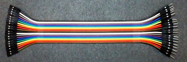
Dupont style jumper wires get their name from the fact that the ends of stranded wire have single male or female connectors crimped to them which were original designed by Dupont.
The stranded wire is usually 24 or 26AWG which provides good flexibility and come in various colors and lengths. The ends are terminated in male/male, male/female and female/female configurations. For breadboard to breadboard jumpers, the male/male terminations are used. The other versions are useful for mating to male headers which are often used on microcontroller boards or breakout adapter modules.
These jumpers are usually bought premade since they are fiddly to make, but the parts are also available to make your own if desired. These are available as packs of single jumper wires, but are also available as multi-colored ribbon cables consisting of up to 40 wires of various lengths that are commonly 4″, 8″ and 12″ in length. These are handy because the ribbon cable is designed to have individual wires or groups of wires stripped from the cable to use as single jumpers or to provide small cables to connect to something such as a sensor module that may require a power, ground and sensor output connections.
U-Shaped Jumper Wires
U-shaped jumper wires are simply wire, usually of 22 AWG gauge that has the insulation stripped at both ends and the stripped ends bent at a right angle for insertion into the breadboard.
These come pre-made in kits with various colors and lengths which are quite handy or they can be made on the fly from a roll of suitable solid conductor wire and a pair of wire strippers.
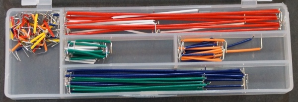
These types of jumpers lie flat to the breadboard and are especially nice when building a semi-permanent circuit since they are not subject to being bumped during handling. The solid conductor wire also keeps its shape once it is put into position. Even when using the Dupont style jumpers for most of the interconnections, these can be useful for running power and ground since it keeps these runs as short as possible and the wire gauge is usually bigger than is used with the Dupont style stranded wires.

Breadboard Pros and Cons
Breadboards are extremely useful for many projects and are practically indispensable for working with Arduino and similar microprocessors but it is important to understand their pros and cons so that you know where they can be applied and where they may not perform as you might expect.
Pros:
- Breadboards provide an inexpensive and easy way to get up and running with an electronic prototyping setup.
- Circuits can be constructed easily and quickly by simply inserting components and wires into the breadboard holes. Jumper wires can also be used to connect that circuit to a microcontroller or other external device as needed.
- No soldering is required.
- Changes to the circuit can be made easily by simply plugging and unplugging components and wires as required.
- Once you are done with the circuit, the components can be easily removed and reused in a new circuit in the future.
Cons:
The cons of breadboards are mainly related to the limitations of the electrical connections that are made by the spring contacts. The quality of those contacts has a significant impact on how big of an issue any of these cons are and we will cover that in detail later.
- Connections are not as robust as soldered connections and are not suitable for circuits put into permanent long-term operation. Vibration or shock to the assembly can cause the connections to fail over time.
- If the breadboard has poor quality contacts, connections may be intermittent if leads are wiggled.
- Connections may have a higher resistance (impedance) than a soldered connection. This impedance is affected by the quality of the contacts used in the breadboard, the size of the component or wire inserted into the contacts and how much usage the contacts have experienced. In some cases, this can be like adding a 5 ohm series resistor to a circuit connection. Whether this small impedance creates an issue for the circuit depends on the type of circuit it is.
- Connections are not suitable for high current flow such as may be required when prototyping something like a power MOSFET circuit. This is largely due to the higher impedance of these connections which can cause resistive heating and the fact that the maximum lead diameter is limited to 20AWG which is too small to handle larger currents. Current is generally limited to around 2A with a good quality breadboard.
- Connections are not suitable for components that rely upon a large ground plane connection to some of their leads for thermal dissipation as may be the case with something like a power amplifier IC that is operating at high power levels. For experimental work with breadboards, these can often be driven at lower levels where heat sinking is not required or a heatsink can be added to the device to help with heat dissipation.
- Connections are not suited for very high frequency work since the stray resistance and capacitance of the leads, spring contacts and jumper wires can introduce some degradation of the waveforms like clock signals as the frequency increases. 1MHz is usually safe and circuits running at up to 10MHz to 16MHz are usually possible if care is taken in the layout and the breadboard is of good quality.
- Connection nodes for some types of circuits need to be kept as short as possible for a circuit to work properly. The breadboard construction technique places limitations on how closely components can be placed and their minimum lead lengths.
While the cons list may seem long, the pros list makes it very attractive to use breadboard construction whenever possible until or unless the specific circuit being worked with demands a different construction method.
When the cons of using a breadboard are too high for the circuit in question, it is common to instead prototype the circuit using a solder type prototype PCB to mount the components. These are more difficult to work with, but they are the only way to build some types of circuits.
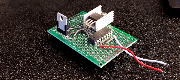
In many cases, a circuit that is destined for a permanent application can be prototyped on a solderless breadboard, then moved to a soldered prototype PCB for final construction once all the kinks are worked out.
For full blown engineering level prototyping of complex circuits, most often custom PCBs are used from the beginning because of the electrical demands and complexity of the parts used.
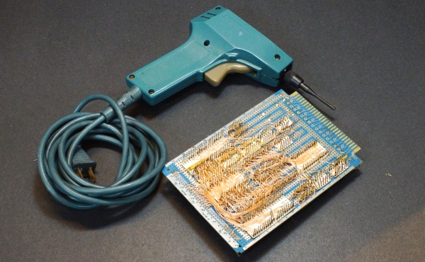
In years past, wire wrapping was a popular method of prototyping that worked well with even large and fairly complex circuits. A hand or power tool was used to tightly wrap small 30 AWG wire around square posts to make the electrical connections. The construction technique was robust and circuit changes could be made moderately easy but alas it is rarely used today.
Breadboard Quality And Features To Consider
If you have shopped for breadboards on someplace like Amazon or Ebay, it is tempting to just buy the cheapest item you find since they all appear to be pretty much the same. Even looking at reviews is usually not of much help since many users of breadboards are casual users that are not doing much past blinking an LED using their Arduino Uno board and pretty much any breadboard will accomplish that task.
The part that mainly defines the quality of the breadboard is the part that you unfortunately can’t see which are the spring contacts. High quality contacts cost more than low quality contacts and that is the main driver of the cost of the breadboard under consideration.
There are other items to think about as well when selecting a breadboard, some more important than others. Here is list of the main items to consider when buying a breadboard. We will go into more detail on each of these below.
- Spring contacts
- Power rail construction
- Plastic housing
- Mechanical mating of multiple breadboards
- Breadboard backing
- Breadboard assemblies with metal plate
- Size and quantity of breadboards to buy
- Supplying Power to the breadboard
Spring Contacts
This item is the main price/performance trade-off decision to be made. Better contacts cost more, but also provide better performance by ensuring good electrical connections between components and will ensure a longer service life of the breadboard.
When shopping between suppliers, higher price does not guarantee that you are getting the higher quality parts but it can be a possible indicator. It tends to be a better indicator when shopping different product lines within the same supplier or ideally if the supplier just provides that info up-front. Unfortunately most suppliers do not provide this info and when it is left out and the price is on the lower side, you should assume lower quality parts are being used.
The spring contacts have 3 main properties to consider:
- Material used in construction
- Physical design
- Spring tension
Materials Used in Construction:
There are 2 main types of materials used in constructing the spring contacts:
- Stainless steel or steel with nickle plating
- Phosphor bronze, beryllium-copper or other copper based alloy spring material with nickle plating
For the sake of brevity, I am going to refer to stainless steel or nickle plated steel as just ‘steel contacts’ and the copper based nickle plated alloys as just ‘copper contacts’ as their properties are similar within those two categories.
If the contacts are removed from the housing, the steel contacts will have a bright silver finish while the copper contacts will tend to have a slight copper or bronze color, especially if viewed from the side. The steel contacts will also tend to be constructed of thicker material.
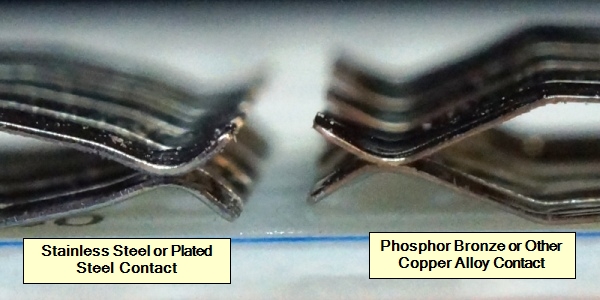
Steel contacts
Steel contacts are the low cost way to construct breadboards. Inexpensive breadboards virtually always will use this type of construction.
Pros: Lowest cost
Cons: Stainless steel and steel in general has a higher resistance over a given distance than a copper based metal like phosphor bronze. Within the 5-pin contacts this resistance is fairly minimal, but on the longer power stripes, the resistance end-to-end can be as much as 10 ohms. If you are drawing much power down the power rail, that can result in a voltage drop that may need to be taken into consideration.
Steel contacts don’t make as positive of an electrical connection as a copper contact do. Inserting a jumper wiring and then wiggling it will show the resistance changing more with a steel contact than it does with a copper contact.
Steel contacts don’t have the same memory properties that a copper contact does. The steel contacts will tend to lose their spring tension quicker with use.
Copper Contacts
Copper contact pros and cons are the opposite of steel contacts. Price is higher, but all electrical properties are better and the copper contacts can withstand many insertion cycles without changing the impedance of the connection.
High copper alloys would provide the best conductivity but they are too soft for use in this application.
The phosphor bronze alloy that is most often used in these contacts produces a very tough contact with a low coefficient of friction and excellent long-term spring properties and provides the best compromise between good conductivity and the ability to withstand repeated insertions.
Beryllium copper is also occasionally mentioned for use in breadboards. It is tougher and has higher conductivity than phosphor bronze, but it also adds significant cost over phosphor bronze so it is seldom if ever used in breadboards.
Conclusion:
Steel contacts provide an entry level solution for anyone looking for a low cost way to get started in the hobby or if using the breadboards in bulk for light duty applications and cost is a major factor. If buying off the internet and the contact material is not specifically called out, it is safe to assume that steel contacts are being used. Our Hobby Line uses stainless steel contacts.
If price is not a major driver and especially for anyone that plans to make significant or serious use of their breadboard and wants to get the optimum performance out of it, then sticking with the high quality copper based contacts is highly recommended. Our Pro Series of breadboards use phosphor bronze contacts and are rated for up to 50,000 insertions. We have tested to 500 insertions with no measurable change in contact resistance.
Physical Design of the Spring Contacts
There are 3 main designs used in forming the spring contacts
- Flat contacts
- Embossed throat contacts
- Fully embossed contacts
Flat contacts are the simplest and cheapest to make. The tops of the contacts are flared out to help guide the lead in but are otherwise flat in shape. When viewed from the top, the opening will look like two parallel lines.
This style of contact provides minimal surface contact area when a round lead is inserted into the contact. It also has the least strength against losing tension with use over time or being permanently damaged when inserting larger leads resulting in that contact on the breadboard becoming unusable.
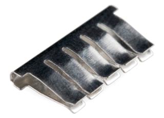
It is best to avoid flat sided contacts when possible.
Embossed Throat contacts are similar to flat sided contacts except that a small embossed feature is added to the throat of the spring contact that creates an oval shaped opening to help guide in the lead and provides more mechanical strength against possible permanent bending of the contact during lead insertion.
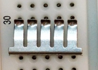
This style of contact is used in most low cost versions of breadboards. They perform adequately if not optimally. Our Hobby Line uses this style of contact.
Fully embossed contacts have a half-round feature embossed not only in the throat of the contact, but which also extends the full length of the contact . This serves several purposes.
- Adds additional strength against permanent bending
- Ensures good spring tension over extended use
- Helps to guide the lead into position
- Adds contact surface area over the length of the inserted lead
- Helps to capture the lead over more of its length and hold the component in position better
Fully embossed contacts are used in the highest quality breadboards and only when using copper based contacts. Steel based contacts would be too stiff with this feature, but it works well with copper based contacts that are inherently more flexible.
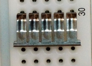
Budget permitting, fully embossed contacts are the best choice. Our Pro Series uses fully embossed contacts as pictured above.
Spring Contact Tension
Spring tension affects the contact pressure applied to the inserted lead and affects how hard it is to insert the lead into the breadboard. While high contact pressure seems like a good thing for making solid connections, it can also make it hard or next to impossible to insert thinner leads without having the leads bend as they are being inserted into the contact and thus be frustrating to use. Too little tension can obviously compromise the electrical connection leading to intermittent electrical contact.
Steel contacts are typically thicker and are inherently less springy than the copper based contacts, so they may show higher insertion force initially and then weaken with use.
Like Goldilocks, a spring tension somewhere between not too firm and not too soft is just about right. You should feel some resistance when inserting a lead, but it should insert fairly easily. Very fine leads may still need some help being inserted. This can usually be accomplished by holding the lead with a pair of needle-nose pliers near the point of insertion while the lead is being inserted into the contact. For best performance, it is recommended to try to use leads of at least 26 AWG to ensure good electrical contact and minimize bending during insertion. 22 AWG is optimal and is typically used for making jumper wires.
Power Rails
Power rails run the length of the breadboard and serve to distribute one or more voltages and ground so that they can be easily jumpered over to the various points in the circuit that require power and ground connections. There are two main things to watch for on power rails
- Do the contacts in the power rail run the entire length of the breadboard or are they split in the middle?
- Are the power rails clearly labeled for power and ground?
For almost all purposes, it is preferable to have the contacts run the entire length of the power rail. If they don’t, you will need to ensure that you provide jumpers to bridge the gap or be left wondering why half your circuit is dead. There may be cases where it is desirable to provide two different voltages such as 5V and 3.3V, but this can usually be done by supplying different voltages to the left and right power rails rather than to the two halves of a single split power rail.
Power rail markings are also important. Most power rails have red and blue lines marking the power and ground connections of the power rail. Typically, red is used for the power and blue is used for the ground. If the red/blue markings show a break in the middle of the power rail, that indicates that the internal contacts also have a break and so it provides a clue to its internal construction which may not be called out in the description of the product.
Some breadboards do not have any markings on the power rails. It is very easy to get confused which rail has voltage on it and which has ground and those are not the type of connection mistakes that you want to make. If the power rails are unmarked, it is usually a good precaution to provide your own markings to avoid making costly mistakes.
The 3 basic power rails types are shown below.
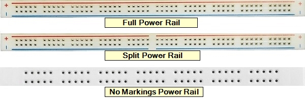
General recommendation is to stick with clearly marked full length power rails unless you have a specific requirement for using something different.
Plastic Housing
The plastic housing has several characteristics to consider:
- Material used in construction
- Color
- Labeling
- Flatness
- Round vs square holes
Material used in construction
ABS Plastic: The vast majority of breadboard housings are constructed of ABS plastic (Acrylonitrile Butadiene Styrene). ABS is a tough plastic that is well suited to this application. The heat resistance is typically listed as 84°C which is the temperature at which the plastic will start to distort. All clear breadboards are made from ABS.
POM Plastic: Some breadboards are constructed of POM plastic (Polyoxymethylene) which is also called Delrin or Acetal. POM has superior mechanical properties to ABS including being harder and stiffer and with a higher heat resistance of 150°C. POM is often used to make the small 170 tie-point breadboards mainly because it can take bright colors better than ABS.
For breadboard applications, the choice of plastic is not a major factor for consideration.
Color of Housing
This is mostly a personal preference kind of thing. Most breadboards are white to an off-white in color. There are also breadboards constructed of clear ABS plastic that allows the silver colored contacts to show.
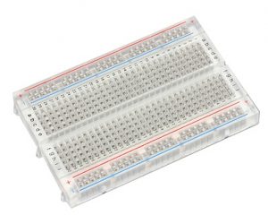
Small breadboards such as the 170 tie-point versions are also often available in various bright colors like red, yellow, green and blue.
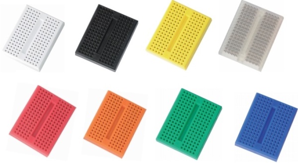
Most people find that the standard white or off-white color makes it easiest to see components and connections though the clear breadboards do have a certain cool look about them. The brightly colored breadboards are sometimes used to color code circuits that they contain or just to provide a splash of color.
Breadboard Labeling
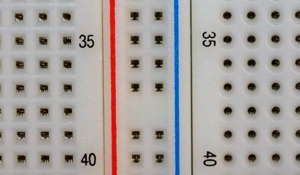
Breadboards have an X/Y coordinate system with the 10 columns of contacts labeled ‘a’ thru ‘j’. The rows are typically numbered ‘1’ thru ‘xx’ with xx depending on the length of the breadboard. Some breadboards label every row while the majority label every 5 rows.
This labeling usually has limited practical value except in an educational environment where it may be desirable for multiple individuals to duplicate a specific breadboard arrangement. In this case a connection can be called out using the grid coordinates such as – Add a wire to connect ‘A1’ to ‘B3’. The same process can also be used document breadboard setups in case a hobbyist wants to document and recreate an exact setup in the future. In that case having every row numbered as shown below can make the process a little less error prone.

Flatness of Housing
Cheaper breadboards may have some amount of bow or warp to the plastic housing from the molding process or storage conditions. A small amount of bow or warp is mainly cosmetic and will not significantly affect the functionality of the breadboard. Because the power rails are often held in place adjacent to the breadboard area using double-sided tape, they can flex relative to the breadboard unless the assembly is mounted to a flat surface.
POM plastic housings will tend to form flatter housing due to the characteristics of the plastic.
Higher quality breadboards like our Pro Series will generally have tighter controls on the molding of the plastic that helps to ensure a flatter assembly.
Round Hole vs Square Hole
Breadboards come in versions that have either square or round lead-in holes to the contacts. This is mainly a slight cosmetic difference with no real difference in how it affects the insertion of leads.
Breadboard to Breadboard Physical Mating
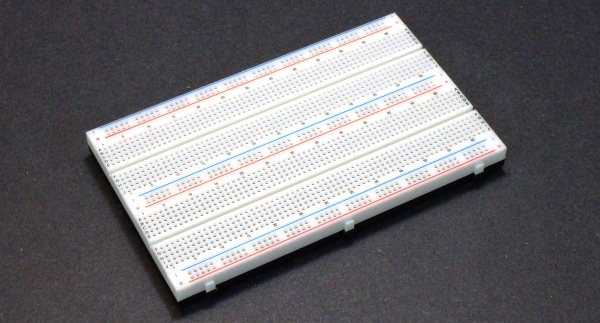
Individual breadboards have small slots and tabs designed to connect the breadboards together mechanically. These may be located on just the long sides of the breadboard or may also be included on the ends as well.
On the lowest cost breadboards, these are usually woefully inadequate to keep the breadboards firmly connected to each other and the adhesive backing will often overlap the slot and interfere with the fit. Higher quality breadboards will generally provide for larger features that provide a more positive latching mechanism and the adhesive backing is kept back from the edges to avoid conflict as shown in our Pro Series example below.

Generally when using more than one breadboard for a single circuit where movement may disrupt the interconnections, it is best to go with the breadboard assemblies that mount several breadboards on a metal plate.
The one exception that I am aware of is our Snap-Lock Line of breadboards where each breadboard is mounted to a plastic base with built-in feet that allows the individual breadboards to be firmly snapped together in a more positive fashion. These are very handy for building scalable breadboards that can be changed in size on the fly depending on the current project size and are robust enough once snapped together to move as an assembly.
Breadboard Backing
Almost all individual breadboards come with a double-sided adhesive tape pad adhered to the bottom of the assembly. This serves primarily to keep the electrical contacts in the housing since they are inserted from the bottom of the plastic housing and could be pushed out if there was nothing to retain them. Since the adhesive tape is somewhat elastic, if heavy force is used to insert a component while the breadboard is held off a surface, it is possible to partially push the contact and adhesive tape down. This can be corrected by pushing the tape and contact back in place. If the breadboard is kept on a flat surface while components are installed, this problem can be avoided.
If the liner is removed from the bottom side of the tape, it can then be adhered to a surface if desired, such as if you are putting several breadboards together to form a larger breadboard area.
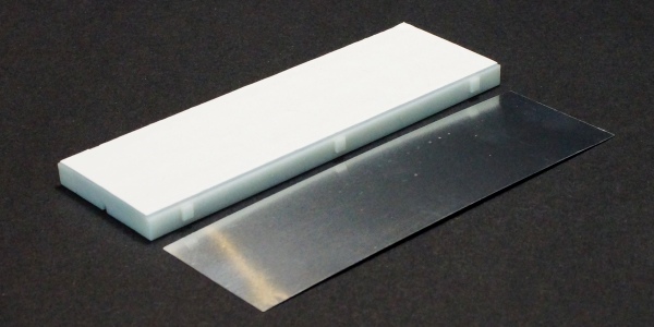
Some breadboards also ship with an aluminum plate that can be adhered to the tape to provide a metal backing to the breadboard if that is desired as shown above. It helps to provide a little more support to prevent the contacts from accidentally pushing through the tape. If a ground wired is added to it, it can also act as a ground plane.
Breadboard Assemblies
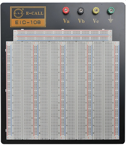
One or multiple breadboards are often mounted to metal plates which are usually made of powder coated or anodized aluminum or steel to provide a larger breadboard surface area.
The smallest versions mount a single 830 tie-point breadboard while the largest commonly available version mounts four of the 830 tie-point breadboards with shared power rails for a total of 3220 tie-points.
When selecting a breadboard assembly there are a few things to consider besides all the stuff that we already covered for individual breadboards such as contact quality.
- Size of Breadboard Assembly
- Electrical Connections to Metal Plate
- Mounting Feet
- Attachment of Breadboards to Metal Plate
Size of Breadboard Assembly
As already noted, these can range from 830 to 3220 tie-points and even larger. Bigger sizes provide more flexibility but also cost more. I recommend going with the largest that your budget comfortably allows unless you are space constrained, as it will provide the most flexibility for circuit size and layout.
Electrical Connections To Metal Plate
Breadboard assemblies always provide a way to connect DC power to the assembly which can then be jumped over to the power rails.
Most commonly these connections are made via banana jack style binding posts with 3 provided on smaller assemblies and 4 or 5 on larger assemblies. These jacks allow banana jack plugs to be used to bring in power and also provide a hole and screw clamp action for clamping down on wires that can be used to jumper power over to the breadboard power rails.
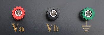
Occasionally you will find breadboards with screw type terminal strips as shown below. These can work well for some applications.

You will also find some cheaply made breadboards that use speaker wire spring clamps. These do not work very well since there is only one spring loaded clamp for connecting both incoming and outgoing power wires. The breadboards that use these also do not use metal plates, but instead use a low quality fiberglass board to mount the components.

There is typically no electrical connection between the binding posts and the metal plate that the breadboards are mounted to. If it is desired to use the plate as a ground plane, the ground binding post or ground on the power rails can be connected to the metal plate.
Mounting Feet
The metal plate will come with rubber feet that may ship unattached. These feet are needed to support the breadboard and protect the surface it is sitting on.
Inexpensive assemblies ship with poor quality small adhesive feet that do not adhere well and are mostly worthless. On our Hobby Line, we toss these poor quality feet and install large beefy high quality feet as shown below.
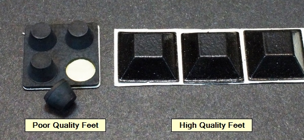
Good quality assemblies use high quality adhesive or screw-on feet. Our Pro Series ships with high quality adhesive feet from the factory.
Attachment Of Breadboards To Metal Plate
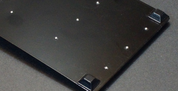
The breadboards should have screws inserted from the bottom side of the metal plate to permanently attach the breadboards even if the double-sided tape is used. This ensures the breadboards stay firmly mounted even as the tape ages over time and may loose adhesiveness. Most if not all breadboard assemblies have this feature including all those found on the ProtoSupplies.com website.
Size and Quantity of Breadboards To Buy
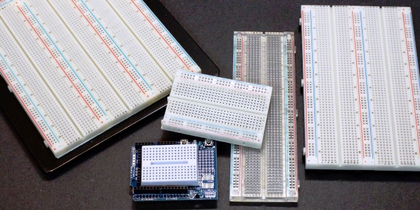
Breadboards come in several different sizes with the 3 most common sizes being tiny ones that have 170 tie-points with no power rail, mid-size 400 tie-point ones with power rails and large 830 tie-point breadboards also with power rails.
To go larger than 830 tie-points you usually must go with an assembly that has several of these breadboards mounted together to a metal plate. These are commonly available in several sizes with up to 3220 tie-points or even larger. There are also some that snap firmly together to provide any size that you need such as our Snap-Lock line of breadboards.
So one question to answer is how big of a single circuit you think you may want to build and another is whether you may want to build several separate circuits at the same time.
Another consideration is whether you need some smaller modules for use with robotic projects. The 400 tie-point size can be useful in that application and many shields are available for Arduino that use the 170 tie-point size and often also include solder type breadboarding areas as well.
In my setup, I use a large 3220 tie-point breadboard for the bulk of my work. It has plenty of room for a single large circuit or a couple of smaller ones since I often have several things going on at the same time.
I also like to have a couple of smaller 400 or 830 size breadboards handy. These are useful for building circuits that I want to keep around for some extended period, but that I don’t want to have tying up my main breadboard.
The tiny 170 size breadboards can be handy for semi-permanently mounting small circuits that are then jumpered over to the main breadboard like functional building blocks without having to wire them up each time.
Supplying power to the Breadboard
Once you have your breadboard setup and have built a circuit on it you will need to supply power to that circuit. Power can come from a variety of sources including:
- Tap from an associated microcontroller board
- Battery or battery pack
- Wall AC/DC adapter
- Breadboard power Module
- AC/DC power supply
- Bench variable power supply
Tap From An Associated Microcontroller Board
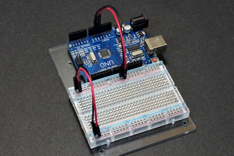
For many setups that are used with something like an Arduino or other microcontroller board, power can be tapped directly from the board and jumpered over to the breadboard to power it up. With an Arduino, the 5V, 3.3V and the Vin voltages as well as ground are all available for powering a circuit.
One thing to keep in mind is that the power being drawn off the microcontroller cannot exceed the maximum current that it can supply. In the case of an Arduino, that generally limits the maximum current to < 500mA on the 5V and 50mA on the 3.3V. The maximum Vin current will depend on how the microcontroller is being powered. If the microcontroller is being powered off a USB port, the total current is usually limited to 500mA including what the microcontroller itself is using so that may limit the 5V to something closer to 300mA.
The other thing to consider is that electrically noisy devices such as motors can cause electrical glitches on the power that can cause issues for the microcontroller resulting in erratic operation. This can sometimes be minimized if a 100uF or larger electrolytic capacitor and 0.1uF ceramic capacitor is added on the breadboard where the power enters from the microcontroller.
Battery Or Battery Pack
Battery power is most useful when it is necessary to make the breadboard portable and use it in locations where there is no easy access to AC power.
Batteries don’t typically come in 5V or 3.3V versions, so it is usually necessary to start with something like a 9V battery and then use a breadboard power module or other method to step the voltage down to 5V or whatever is needed.
9V batteries are small and convenient to use, but they cannot supply much current. If the circuit draws much power at all, it is better to go with a battery pack that uses 6 AA type batteries or something similar that also produces 9V, but that has a much higher current capability.
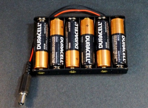
If the breadboard is being used with a microcontroller, the battery pack is usually used to power the microcontroller and the power from the microcontroller is jumpered over to the breadboard.
Wall AC/DC Adapter
Also known as wall bugs, these can be very useful for powering a breadboard. They are available with 5V outputs and will need a DC power jack adapter of some type to mate it to a breadboard setup.
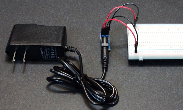
One thing about wall adapters is that the power is not as clean as you would get from other power sources and the voltage output can be on the high side under low load and then drop quite a bit as a heavier load is applied.
In most cases, it is best to use a higher voltage wall adapter in conjunction with a breadboard power module to drop the voltage down and provide good voltage regulation for the circuit.
Breadboard Power Module
Breadboard power modules are usually designed to plug directly into the power rails of a breadboard. A DC voltage of 7-12V is brought in from a wall adapter or other DC power source and the breadboard power module uses regulator ICs to drop the voltage down to 5V and usually also provides 3.3V. These module can also often be powered from a USB port.
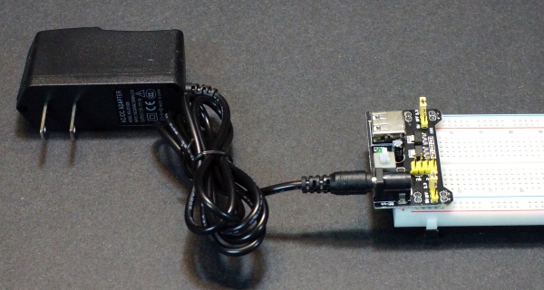
There are several versions commonly available and are very inexpensive for the functionality that they provide.
One thing to keep in mind is that the linear regulator used on these modules have to dissipate the extra power as they drop the voltage down from the input voltage to the 5V output. For that reason it is best to power these from a lower voltage such as a 7.5V rather than a 12V wall adapter if you want to optimize the amount of power that they can provide to the breadboard.
AC/DC Power Supply
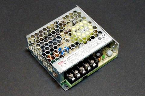
These are fixed voltage output supplies that can supply a lot of current. They are primarily designed to be embedded in products but also work well as bench supplies to power circuits that require more than just a little power to operate.
When using these types of power supplies, ensure that they are enclosed, as shown below, rather than open frame to minimize the risk of electrical shock. Care still needs to be taken around the AC screw terminals. Meanwell power supplies are good examples of these types of power supplies and are available in a number of output voltages such as 5V and 12V and are also available with multiple output voltages such as 5V, +12V and -12V.
You do need an AC power cord to power the device as well as wires to get the DC power from the supply screw terminals over to the breadboard.
Bench Variable Power Supply
The holy grail but also the most expensive option is to use a lab style bench variable power supply to power the circuit. These often have more than one output voltage that can be adjusted over a range of voltages such as 0-32V. The one shown here is the Siglent SPD3303X which is one we use and can recommend. It also has a fixed output that can be set for 2.5V, 3.3V or 5V so it can provide up to 3 different voltages.
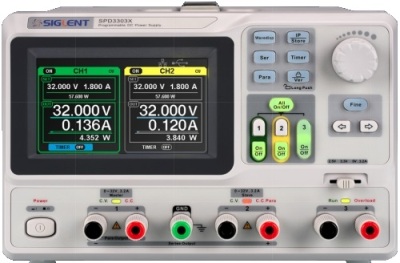
The main benefits of this type of power source are that the output voltage(s) can be set to whatever you need which might be handy if you are using a range of voltages in the circuit or you need both a positive and negative voltage such as for some analog circuits.
Another very useful feature is that most of these types of power supplies also have an adjustable current limit. When pushing boundaries, it can sometimes be very useful to limit the maximum amount of current that can be drawn from the power supply to avoid damage to components.
Wiring Up The Power
One last thing to consider is the wiring that is used to connect power to the breadboard and the individual breadboard power rails.
If you just wired up the mother of all circuits on a large breadboard assembly and then run a long 22 AWG jumper wire to bring over power and ground, you might be in for a surprise at just how much voltage drop and heating can occur in that wire. Breadboards are very handy tools, but they can’t circumvent Ohms law.
For small setups, the exact power wiring used will usually have minimal impact and just getting power and ground to the correct place is all that is needed. As the circuit size increases and current demands grow, the wiring for the power can become more important and consideration needs to be made to ensure that wires are of adequate gauge and the lengths are not longer than necessary to avoid excessive voltage drops or heating of the wire.
The main power lead from the power source to the breadboard should be sized appropriately for the total power draw. A large setup using a breadboard assembly may benefit from an 18 AWG or larger gauge wire to get from the power supply to the binding posts depending on how far the lead needs to run.
Once on the breadboard, the power will need to be jumpered to any power rails. For a larger breadboard assembly with binding posts, several 22AWG wires may need to be run from the binding post to the breadboard power rails.
For our setup we make a cable that plugs into the binding post using a banana plug and that terminates into a male header on the other end so that there is a heavy gauge connection from the binding post to the distribution power rail. That setup requires that the main power comes in on a stackable banana plug.
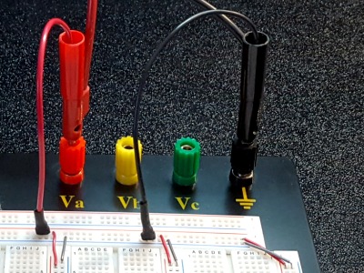
From there 22 AWG wires are used to connect to the individual power rails. A single 22AWG wire for each power rail voltage and ground is usually adequate, but if the circuit is power hungry, a couple of 22AWG wires can be used in parallel to ensure minimal voltage drop.
If the circuit tends to draw its power in spurts and the wiring is not quite up to the task to avoid excessive voltage drops, adding a bulk capacitor to the power rails can sometimes help by providing a local store of power.
