


1-Channel Relay Module 5V — 10A SPDT, Active-Low, Opto-Isolated, Arduino Compatible
1-Channel Relay Module 5V 10A SPDT, Active-Low, Opto-Isolated, Arduino Compatible
Compatible JST cables for sensors and modules — secure & reliable. Shop now.

Couldn't load pickup availability
1-Channel Relay Module — 5V, 10A SPDT, Active-Low Control, Arduino Compatible
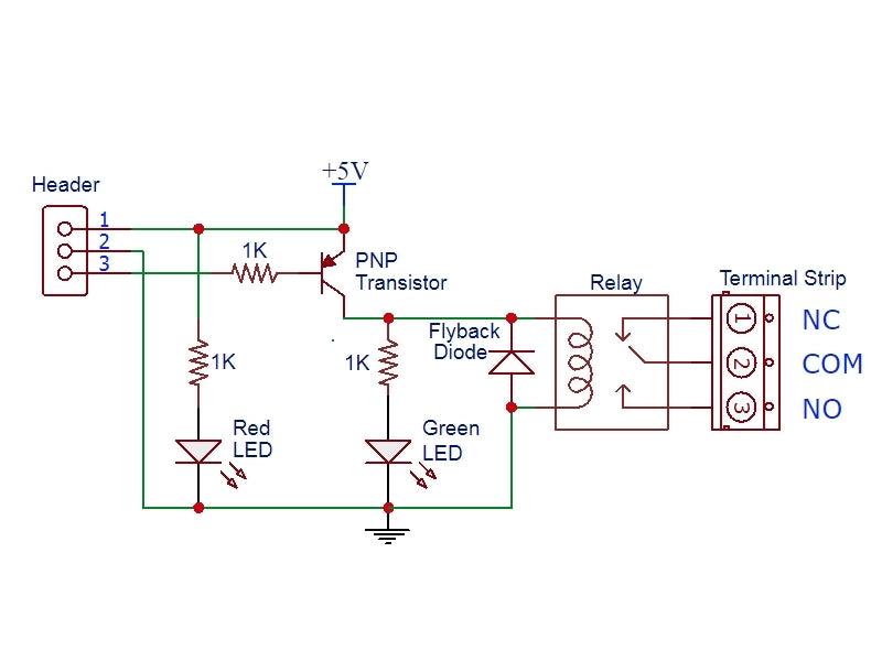
The 1-channel 5V relay module is the most widely used relay module in Arduino and ESP32 projects worldwide — a complete, ready-to-use relay circuit on a single PCB. Connect 5V power, wire your load to the relay screw terminals, and control the relay with any Arduino digital output pin. The onboard transistor driver means the relay coil is driven by the module, not the MCU pin — only ~5mA from the GPIO pin is needed to switch a 10A load.
The relay is active-LOW: a logic LOW signal on IN1 energizes the relay (green LED ON, audible click). Logic HIGH or no connection de-energizes the relay. Both NO (Normally Open) and NC (Normally Closed) contacts are available on the screw terminal block.
Key Features
- 10A SPDT relay contacts — switches up to 250VAC @ 10A or 15VDC @ 10A
- Active-LOW control — logic LOW energizes relay; logic HIGH de-energizes
- Onboard transistor driver — only ~5mA from GPIO needed; safe for all MCU pins
- Both NO and NC contacts — switch load ON or OFF when relay energizes
- Green LED indicator — illuminates when relay is energized
- Red power LED — confirms 5V supply connected
- Built-in flyback diode — protects driver transistor from relay coil back-EMF
- Screw terminal block — secure load wiring without soldering
- 3-pin header — GND / IN1 / VCC for direct Arduino connection
Technical Specifications
| Supply Voltage | 5V DC |
| Supply Current | ~80mA when relay energized |
| Control Logic | Active-LOW (LOW = relay ON) |
| GPIO Current Required | ~5mA (transistor driver onboard) |
| Relay Contact Rating (AC) | 125VAC @ 10A / 250VAC @ 10A |
| Relay Contact Rating (DC) | 15V DC @ 10A (recommended max) |
| Relay Type | SPDT (NO + NC + COM) |
| Logic HIGH threshold | ≥4.2V (relay de-energizes) |
Wiring Guide
Control header (3-pin):
- GND → Arduino GND (must share ground with MCU)
- IN1 → Arduino digital output pin (LOW = relay ON)
- VCC → 5V supply
Load screw terminal (3-pin):
- NO → Load terminal that connects to COM when relay energizes (IN1 LOW)
- COM → AC or DC power source for the load
- NC → Load terminal that connects to COM when relay is de-energized (IN1 HIGH)
Active-LOW Logic — Important
This module uses active-LOW control: digitalWrite(relayPin, LOW) turns the relay ON; digitalWrite(relayPin, HIGH) turns it OFF. This is the opposite of what many beginners expect. The logic HIGH threshold is ~4.2V — a pull-up resistor may be needed if the control signal is from an open-collector output or if the GPIO voltage is below 4.2V at HIGH.
DC Voltage Limit
The relay contacts are rated 30VDC on the relay body markings, but DC arc suppression is poor above ~15V. Contacts can become sticky or weld at higher DC voltages. Limit DC switching to 15V or below. For AC switching, the module handles up to 250VAC @ 10A reliably (tested at 1500W / 12.5A heater load).
Typical Applications
- Arduino home automation — control lights, fans, appliances from GPIO
- ESP32 / ESP8266 IoT relay control via Wi-Fi or MQTT
- Raspberry Pi GPIO relay switching (with 3.3V–5V level shifter)
- Automatic irrigation solenoid valve control
- 12V DC motor and pump on/off control
- Security system alarm and siren activation
- Temperature-controlled fan and heater switching
Package Contents
- 1 × 1-Channel Relay Module 5V (10A SPDT, active-low, with screw terminals)


Blog posts
View all-

Best JST Connector Crimping Tools in 2026: Engi...
Choosing the wrong crimping tool ruins JST connectors and wastes wire. This guide compares the top crimping tools for JST SH, GH, PH, XH, and VH series — including Engineer...
Best JST Connector Crimping Tools in 2026: Engi...
Choosing the wrong crimping tool ruins JST connectors and wastes wire. This guide compares the top crimping tools for JST SH, GH, PH, XH, and VH series — including Engineer...
-

Molex KK 254 vs Mini-Fit Jr. vs Micro-Fit 3.0: ...
Choosing between Molex KK 254, Mini-Fit Jr., and Micro-Fit 3.0? This guide compares pitch, current rating, locking mechanism, wire gauge, and typical applications — with decision tables, part number references,...
Molex KK 254 vs Mini-Fit Jr. vs Micro-Fit 3.0: ...
Choosing between Molex KK 254, Mini-Fit Jr., and Micro-Fit 3.0? This guide compares pitch, current rating, locking mechanism, wire gauge, and typical applications — with decision tables, part number references,...
-

DuPont Connector vs JST PH 2.0: Pinout, Specs &...
Not sure whether to use a DuPont 2.54mm or JST PH 2.0mm connector? This guide compares pitch, locking mechanism, current rating, pinout, and best use cases — so you can...
DuPont Connector vs JST PH 2.0: Pinout, Specs &...
Not sure whether to use a DuPont 2.54mm or JST PH 2.0mm connector? This guide compares pitch, locking mechanism, current rating, pinout, and best use cases — so you can...


