Keszoox
10PCS IRF3205 TO-220 N-Channel MOSFET 55V 110A for Inverter Applications
10PCS IRF3205 TO-220 N-Channel MOSFET 55V 110A for Inverter Applications

Couldn't load pickup availability
IRF3205 TO-220 N-Channel Power MOSFET — 55V / 110A / 8mΩ, 10 Pieces
The IRF3205 is one of the most widely used N-channel power MOSFETs in power electronics, combining an exceptionally low on-resistance of 8mΩ with a 110A continuous drain current rating in the standard TO-220 through-hole package. Originally from International Rectifier (now Infineon), the IRF3205 is the go-to device for high-current low-side switching in inverters, motor H-bridges, synchronous buck converters, and battery management systems.
10 pieces per pack. New, original parts.
Key Specifications
- Part Number: IRF3205 / IRF3205PBF
- Channel Type: N-Channel
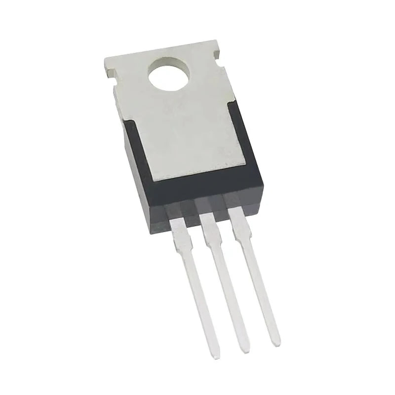
- Package: TO-220 (through-hole, tab = Drain)
- Drain-Source Voltage (Vds): 55V
- Continuous Drain Current (Id): 110A @ 25°C (75A @ 100°C)
- On-Resistance Rds(on): 8mΩ @ Vgs=10V (one of the lowest in TO-220 class)
- Gate Threshold Voltage (Vgs(th)): 2V – 4V
- Total Gate Charge (Qg): 110nC @ Vgs=10V
- Power Dissipation (Pd): 200W (with heatsink)
- Body Diode Forward Voltage: 1.3V @ 55A
- Operating Temperature: −55°C to +175°C
- Quantity: 10 pieces
TO-220 Pinout
- Pin 1 (left): Gate (G)
- Pin 2 (center): Drain (D)
- Pin 3 (right): Source (S)
- Tab (metal): Drain (D) — electrically connected to pin 2; use insulating pad when mounting to grounded heatsink
Gate Drive Requirements
- Full enhancement: Vgs = 10V — achieves rated 8mΩ Rds(on)
- Logic-level operation: Vgs = 4.5V — partially enhanced; Rds(on) increases to ~15–20mΩ. Not recommended for high-current applications without full 10V gate drive.
- Arduino/5V MCU: Use a gate driver IC (e.g., IR2104, TC4420, UCC27524) or NPN transistor gate drive circuit to achieve 10V Vgs from 5V logic
- Gate resistor: Add 10–22Ω series gate resistor to limit switching speed and reduce EMI/ringing
Thermal Management
- At currents above 20A, a heatsink is required. TO-220 thermal resistance junction-to-case: 0.75°C/W
- Apply thermal compound between MOSFET tab and heatsink surface
- Use insulating mica or silicone pad if heatsink is grounded (tab = Drain, not GND)
- At 110A continuous, power dissipation = I² × Rds(on) = 110² × 0.008 = 96.8W — requires substantial heatsinking
- For practical circuits, derate to 50–60A continuous with adequate heatsinking for reliable long-term operation
IRF3205 vs. IRFZ44N vs. IRF540N
- IRF3205: 55V, 110A, 8mΩ — highest current, lowest Rds(on) in 55V class. Best for high-current inverters and motor drives.
- IRFZ44N: 55V, 49A, 17.5mΩ — lower current, higher Rds(on). Logic-level gate threshold (Vgs(th) = 2–4V). Better for lower-current applications with 5V gate drive.
- IRF540N: 100V, 33A, 44mΩ — higher voltage rating, lower current. For 48V–72V bus applications.
Complementary P-Channel Pair
The complementary P-channel MOSFET for H-bridge designs is the IRF4905 (55V, 74A, 20mΩ). Together, IRF3205 (low-side N-channel) + IRF4905 (high-side P-channel) form a matched complementary pair for full H-bridge motor driver circuits.
Typical Applications
- DC-AC Inverter: Low-side switching in 12V/24V to 220V push-pull or H-bridge inverter (paired with SG3525A PWM controller)
- H-Bridge Motor Driver: Low-side N-channel switches in full H-bridge for bidirectional DC motor control
- Synchronous Buck Converter: Low-side synchronous rectifier in high-current DC-DC converter
- Battery Management System (BMS): Discharge MOSFET in lithium battery pack protection circuit
- Electronic Load: Linear or PWM-controlled current sink for battery testing
- Solar MPPT Charge Controller: Low-side switch in buck converter power stage
- High-Current Load Switch: 12V/24V power rail switching for industrial equipment
Package Contents
- 10 × IRF3205 TO-220 N-channel power MOSFET