

- ★Product Description
- ★About us
- ★Custom cable
DESCRIPTION
If you want to embed a microcontroller into a project and are looking for something smaller and cheaper than an Arduino and you don’t need a lot of I/O pins or code space, the ATtiny85 can be a good solution.
PACKAGE INCLUDES:
- ATtiny85 Module with Micro USB
- 1 x 9 male header
KEY FEATURES OF ATTINY85 MODULE WITH MICRO USB:
- Atmel ATtiny85 processor running at 16.5MH
- Micro USB connector for easy programming
- 8KB Flash memory, 6K program space
- 6 Digital I/O
- 3 PWM shared with the digital I/O
- 4 Analog inputs shared with digital I/O
- I2C and SPI interface shared with digital I/O
- External interrupt capability
- 3-5.5V or 7-12V Operation
The ATtiny85 is an 8-bit Atmel ATtiny85 MCU from the same AVR family that the Arduino boards are based on. Though it only has 8 pins, it packs quite a lot of functionality into that small package.
The device can be programmed using the Arduino IDE and much of the standard Arduino software and existing libraries will work with it. Other libraries have been modified to work properly with the ATtiny85.
Power
The module can be powered off the USB connector as with any Arduino boards that have USB connectors.
The 5V pin can accept a 3.0 – 5.5V input if you want to power the module directly off 5V or a battery pack in that range. This range is determined by the ATtiny85 chip operating range. If you are instead using the VIN pin to power the module, then you can use this pin as a 5V output to power a sensor or other device.
The VIN pin can accept 7-12V. This input powers an on-board 5V regulator. Higher input voltages can be used up to at least 24V as long as you aren’t drawing much power from the 5V regulator or it will overheat. A current draw of 100-200mA should be fine. You can use the finger test to determine if you are driving the regulator too hard.
USB Interface
The module uses pins 3 & 4 for USB communications. Pin 3 has a 1.5K pull-up resistor which is required for the USB communications. These pins are in parallel with the USB connector that is on the module.
If you don’t need to use these pins in your circuit, life can be easier to leave them free so that you can easily reprogram the device. If you do use these pins in your circuit and if the circuit may interfere with the USB communications, ensure that you can disconnect the circuit temporarily in the event that you need to reprogram the device.
I2C Interface
The I2C interface is connected to pin 0 (SDA) and pin 2 (SCL).
The standard I2C Arduino library will not work with the ATtiny85. We use the TinyWireM.h library in our example below.
SPI Interface
The SPI interface is connected to pin 0 (MOSI), pin 1 (MISO) and pin 2 (SCK).
When connecting the SPI interface, the pins are cross-connected, so the ATTiny85 MISO pin would connect to the external device MOSI and the ATTiny85 MOSI would connect to the external device MISO.
Digital I/O
All 6 pins are capable of digital I/O.
The I/O port on the ATtiny85 chip is Port B and that is why digital I/O are labeled PB0 – PB5 on the backside of the board (and P0-P5 on the front side). These correspond to digital I/O D0-D5 on an Arduino and are referenced in the program using just the number as in pinMode(0, OUTPUT);
Pin 0 is also used for I2C (SDA) and SPI (MISO)
Pin 1 is also connected to SPI(MOSI) and the on-board LED via a 1K pull-down resistor.
Pin 2 is also used for I2C (SCL) and SPI(SCK)
Pins 3 & 4 also used for USB and are limited to 3.6V via Zener diodes.
Pin 5 primary function is as a Reset pin (active LOW), but can be used as a weak I/O pin. The output voltage is limited to about 3V for a logic HIGH. In most cases, this is sufficient to be interpreted as a logic HIGH by 5V inputs. This pin also has a lower current drive capability. To externally reset the processor, this pin can be pulled low.
The internal pull-up resistors if used are turned on by calling digitalWrite(0) after the pinMode is set as INPUT. The pull-ups are fairly weak at about 25K ohms, so the on-board LED on pin 1 can interfere with the pull-up on that pin. If that is a problem, the LED can be removed or the trace to it cut.
Analog Outputs
The ATtiny85 supports PWM on pins 0, 1 & 4.
Pins 0 & 1 PWM operates at 504Hz while pin 4 operates at a higher 1007Hz.
Analog Inputs
The ATtiny85 has a built-in 10-bit ADC and can read analog voltages on 4 of the pins.
When using the analogRead command, refer to the analog input #, not the digital number as shown below, so analogRead(0) reads the analog voltage on the pin labeled P5.
- Analog input 0 = P5
- Analog input 1 = P2
- Analog input 2 = P4
- Analog input 3 = P3
Module Assembly
This module comes with the header loose. It can be snapped into a 6-pin and 3-pin length before soldering to the board.
This allows you to configure the module to meet your particular requirements such as which side of the board you want the headers on or if you prefer to solder on wires to make the connections instead. For use with breadboards, we put the I/O header on the bottom so that the module can plug directly into the breadboard and the power header on top so that jumpers can be used to make power connections.
Module Connections
1 x 3 Header
- 5V = 3V -to 5.5V input or can uses as 5V output if VIN input is used for supplying power
- GND = Connects to ground
- VIN = 7V to 12V input typical. Can be up to 24V.
1 x 6 Header
- P0 = Digital I/O 0, PWM, I2C (SDA), SPI (MOSI)
- P1 = Digital I/O 1, PWM, SPI (MISO)
- P2 = Digital I/O 2, Analog input 1, I2C (SCL), SPI (SCK)
- P3 = Digital I/O 3, Analog input 3, USB
- P4 = Digital I/O 4, Analog input 2, USB / PWM
- P5 = Digital I/O 5, Analog input 0, Reset input (active LOW)
PROGRAMMING
You can program the ATtiny85 using the Arduino IDE. The basic steps are presented here. There is a link to an excellent video at the end of this section that explains the process of getting your environment setup in great detail.
Setting up your programming environment
Here are the basic step to get up and running with the Arduino IDE:
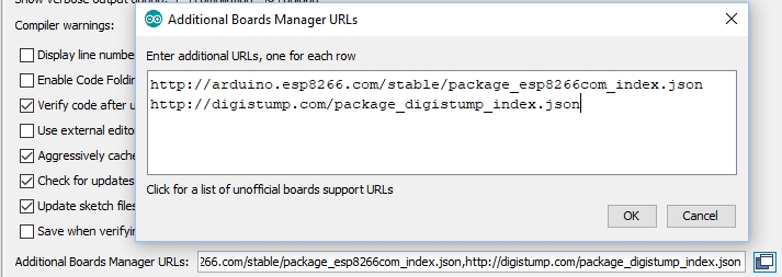
1> Add the following link in Arduino IDE / Preferences / Additional Boards Manager URLS: http://digistump.com/package_digistump_index.json. If you already have other boards loaded, just add this link on a new line as shown here.

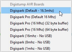
2> Go to the IDE Board Manager and install the Digistump AVR Boards as shown below.

3> Restart the IDE, go to the Board list and select Digispark (Default – 16.5mhz) from the list of boards.

If you need to download a driver for the USB to connect to the ATtiny85 module, it can be downloaded from this link: http://github.com/digistump/DigistumpArduino/releases
Unizip the file into a directory of your choice and run the installer. For Windows use DPinst64.exe for a 64-bit operating system or DPinst.exe for a 32-bit operating system.
If everything goes as planned, when you plug the ATtiny85 into the computer using a Micro USB cable, you will see the device recognized as Digispark Bootloader in the Windows Device Manager window.

If you are new to the ATtiny85, or have any issues with getting the programming environment up and running it is highly recommended that you watch this excellent video as it answers most of the questions that may come up: https://www.youtube.com/watch?v=MmDBvgrYGZs
Downloading Programs to the ATtiny85 Module
One unique feature of programming the ATtiny85 module is that you do not select a COM port to communicate to it with. Instead you follow these basic steps:
1> Ensure the module is unplugged from the USB.
2> Press the upload button on the IDE to compile the program.
3> When the compile completes successfully, you will see this message to plug the device in now…. (will timeout in 60 seconds)

4> You will then have 60 seconds to plug the module into the USB. Once it is plugged in, the system finds it automatically and downloads the software to it. Once that is complete you will see a message from the Micronucleus downloader showing that it is done.

At this point your module will be executing the program.
Note that the bootloader on the module operates for the first 5 seconds when the module is first powered up to see if a new program needs to be downloaded. If you are reprogramming it in a circuit where it is getting external power other than from the USB, you will need to turn the external power off so that it is powered up when the USB download cable is plugged in.
Below is a simple binky program to test your programming setup with. It blinks the on-board LED every second.
/*
ATTiny85 Blinky
Blink the on-board LED of the ATTiny85 module
*/
void setup() {
  pinMode(1, OUTPUT); // Onboard LED is connected to pin 1
}
void loop() {
  digitalWrite(1, HIGH);   // turn the LED on (HIGH is the voltage level)
  delay(1000);             // wait for a second
  digitalWrite(1, LOW);    // turn the LED off by making the voltage LOW
  delay(1000);             // wait for a second
}
OUR EVALUATION RESULTS:
These are nice assemblies with good build quality. The ATtiny85 can be quite fun to play with and inexpensive and small enough to embed into many types of projects.
The main challenge is maximizing the use of the available I/O as all of the pins have multiple uses. In our example here we are just using pins 0-2, leaving pins 3 & 4 open so that we can easily plug in the USB cable to download new versions of software without disconnecting anything. Pin 5 is mainly a reset input and though it can sometimes work OK as an I/O pin, it doesn’t always work due to its low voltage and current capabilities. We initially tried to use it for the DH22 link and it did not work for that purpose.
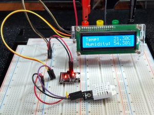
Our example here creates a simple temperature and humidity display. The LCD display uses I2C communications and the DHT22 humidity/temperature sensor uses a library to communicate using one pin.
Some libraries that come with the Digistump download are standard libraries that have been modified to work with the ATtiny85, but still have the same name. For example, our program is using the LiquidCrystal_I2C.h library which has been modified to work with the ATiny85. If you are getting errors because the program is not finding the correct library to use, simply copy the LiquidCrystal_I2C.h and LiquidCrystal_I2C.cpp files from the Digistump download location to the same folder as the ATtiny85 sketch. The parenthesis around the library name in the program below tell the compiler to look in the current directory for the files.
The standard DHT.h library for reading the DH22 sensor works fine with the ATtiny85.
The following connections are needed:
- Pin 0 – Connect to LCD I2C (SDA)
- Pin 1 – Connect to DH22 (or DH11) sensor output pin
- Pin 2 – Connect to LCD I2C (SCL)
- Pins 3 – 5 are not used.
Also connect a source of 5V power for the LCD and DH22. In our setup here, we are using a 5V power supply to supply power to the LCD display, DH22 sensor and the ATtiny85 module.
For programming, you will just use the USB cable to supply power to the ATtiny85 module.
ATTiny85 Weather Station Program
/*
  ATTiny85 Weather Station
  Uses a 16x2 LCD with I2C interface and DHT22 or DHT11 humidity sensor
*/
#include <TinyWireM.h>
#include <USI_TWI_Master.h>
#include "LiquidCrystal_I2C.h"  // Put new DigisparkLCD version of this library
                                // in the same folder as the sketch
#include <dht.h>                // Include the DHT library for humidity sensor

int const DHT22_PIN = 1;      // Connects to sensor I/O, use any digital pin

LiquidCrystal_I2C lcd(0x27,16,2);  // set I2C address, 16 chars, 2 line Display
dht DHT;                      // Create instance of DHT object
//===============================================================================
//  Initialization
//===============================================================================
void setup() {
  TinyWireM.begin();                    // initialize I2C lib
  lcd.init();                           // initialize the lcd
  lcd.backlight();                      // Turn on the backlight
  lcd.setCursor(0,0);     //Set cursor to char 0, line 0
  lcd.print("Temp:");
  lcd.setCursor(0,1);     //Move cursor to char 0, line 1
  lcd.print("Humidity:");
}
//===============================================================================
//  Main
//===============================================================================
void loop() {
  int sensor = DHT.read22(DHT22_PIN);  // Read sensor

  lcd.setCursor(10,0);
  lcd.print(DHT.temperature); lcd.print("C");
  lcd.setCursor(10,1);
  lcd.print(DHT.humidity); lcd.print("%");
  delay(2000);                  // DH22 requires 2 Sec delay between reads
}
BEFORE THEY ARE SHIPPED, THESE MODULES ARE:
- Sample inspected and tested per incoming shipment using ‘Blink’ example program.
FURTHER READING:
Notes:
- None
TECHNICAL SPECIFICATIONS
| Microcontroller | Atmel ATtiny85 | |
| 5V Input Operating Voltage Range | 3 – 5.5V | |
| VIN Input Voltage (recommended) | 7-12V | |
| Digital I/O Pins | 6 | |
| PWM I/O Pins (Shared with Digital I/O) | 3 | |
| Analog Input Pins (Shared with Digital I/O) | 4 | |
| DC Current per I/O Pin | 20mA | |
| Flash Memory | 8 KBytes | |
| SRAM | 512 Bytes | |
| EEPROM | 512 Bytes | |
| Clock Speed | 16.5MHz | |
| Power Consumption (Max for Package) | 200mA | |
| Built-in LED | Attached to digital I/O Pin 1 | |
| USB Connector Style | Micro-B Female | |
| Board Dimensions (PCB) | 25x 19mm (1 x 0.75″) | |
| Country of Origin | China | |
| Datasheet | AVR ATtiny85 |


