

- ★Product Description
- ★About us
- ★Custom cable
Bi-polar stepper motor driver that can handle up to 2.2A
DESCRIPTION
The DRV8825 High Current Stepper Motor Driver Module can drive one bipolar stepper motor of up to 2.2A.
PACKAGE INCLUDES:
- DRV8825 High Current Stepper Motor Driver Module
- Heatsink with 3M double-stick adhesive applied.
KEY FEATURES OF DRV8825 HIGH CURRENT STEPPER MOTOR DRIVER MODULE:
- 2.2A current handling capability
- Small footprint
- Easy step and direction control interface
- Six different step resolutions: full-step, half-step, 1/4-step, 1/8-step, 1/16-step, and 1/32-step
- Adjustable current control lets you set the maximum current output with a built-in potentiometer. That allows you to use voltages above your stepper motor’s rated voltage to achieve higher step rates
- Adjustable current decay modes.
- Built-in regulator so no external logic voltage supply is needed
- Can interface directly with 3.3 V and 5 V systems
- Over-temperature shutdown, over-current shutdown, and under-voltage lockout with FAULT pin output
- Short-to-ground and shorted-load protection
- Exposed solderable ground pad below the driver IC on the bottom of the PCB can be used to enhance the cooling if desired.
The DRV8825 stepper motor driver can drive one bipolar stepper motor at up to 2.2A with adequate cooling. The module can easily handle 1.5A with no heatsink. A small heatsink is included and with a little air flow, it can handle up to the full 2.2A. Note that the driver IC can handle up to 2.5A, but the 0.1 ohm current sense resistors limit the output to 2.2A.
It is packaged onto a small board with male headers installed in a wide DIP-16 footprint that makes it breadboard compatible or it can be mounted into a socket. These are often used for precision control of stepper motors used in applications such as 3D printers or robotics.
Power Connections:
The module operates at a voltage of from 8.2 to 45V. Power is connected across the VMOT (Voltage Motor) pin and ground. Note that though the driver operates at these voltages, stepper motors rated at lower voltages can be driven as long as the current limit is set for the motor that is being driven.
It is recommended that an electrolytic cap of 100uF or so size be placed across the VMOT and ground close to the module. This becomes more important as the wiring form the driver to the motor increases in length. This is to help protect against LC induced voltage spikes that can exceed the 45V rating of the IC and cause damage.
Motor Connections:
These are primarily designed to drive bipolar stepper motors with 4 wires. In this case, one winding is connected across the 1A & 2A connections and the other winding is connected across the 1B & 2B connections.
Current Limit Adjustment:
The module has active current limiting. This allows the module to drive the motor at higher then rated voltages to achieve high step rates.
There is a trimmer potentiometer on the board which is used to set the current limit. You will typically set the drivers current limit to be at or lower than the current rating of the motor.
To set the current limit, you measure the reference voltage and adjust it using the formula Current Limit = VREF x 2. As an example, if your motor is rated for 1.2A, you would adjust the reference voltage to 0.6V if you wanted to have maximum current.
The reference voltage can be measured on the metal trimmer pot itself or on the two IC pins near the pot that look like they have a solder bridge. One easy way to make the adjustment is to use an alligator clip on the shaft of a small metallic screwdriver and attach that to your DVM so you can both probe and adjust the voltage at the same time with the screwdriver.
To make the adjustment, you should have the motor connected and operating in full step mode.
Note that the motor coil current will be very different from the power supply current. Typically the power supply voltage will be higher and the current lower than the voltage and current delivered to the motor coils, so you should not use the current measured at the power supply to make this adjustment.
Step Size:
Stepper motors have a set step size which is typically 1.8 degrees (200 steps per full revolution). Microstepping drivers such as the DRV8825 allows for higher resolutions by allowing intermediate step movements. This is achieved by energizing the coils with intermediate current levels. For example, driving a motor in 1/4 step mode will give a 200 step-per-revolution motor an 800 step resolution instead.
The step size is selected using the mode selector inputs (MODE 0, MODE 1, MODE 2) as shown in the table below. These inputs have 100K pull-down resistors, so if they are left unconnected the driver operates in Full Step mode by default.
If microstepping is desired, the MODE inputs can be pulled high using a 10K or similar resistor if a fixed microstepping mode is being used or they can be dynamically driven using output pins on the microcontroller so that they modes can be changed on -the-fly.
The table below shows the microstepping modes that are available.
| MODE 0 | MODE 1 | MODE 2 | Microstep Resolution |
| 0 | 0 | 0 | Full Step (default) |
| 1 | 0 | 0 | Half Step |
| 0 | 1 | 0 | 1/4 Step |
| 1 | 1 | 0 | 1/8 Step |
| 0 | 0 | 1 | 1/16 Step |
| 1 | 0 | 1 | 1/32 Step |
| 0 | 1 | 1 | 1/32 Step |
| 1 | 1 | 1 | 1/32 Step |
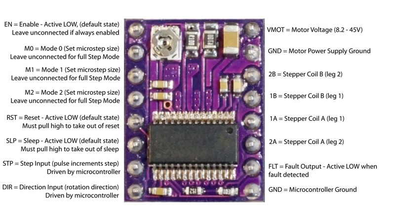
There are 16 pins available on the module as shown below:

OUR EVALUATION RESULTS:
These stepper motor drivers pack a lot in a small package. They work great with our 1.2A stepper motors and will work well with any bipolar stepper motors up to their current limit of 2.2A.
When using with an Arduino, the BasicStepperDriver.h library can be downloaded from GitHub which provides control for the DRV8825 and similar stepper drivers and is used in our program below.
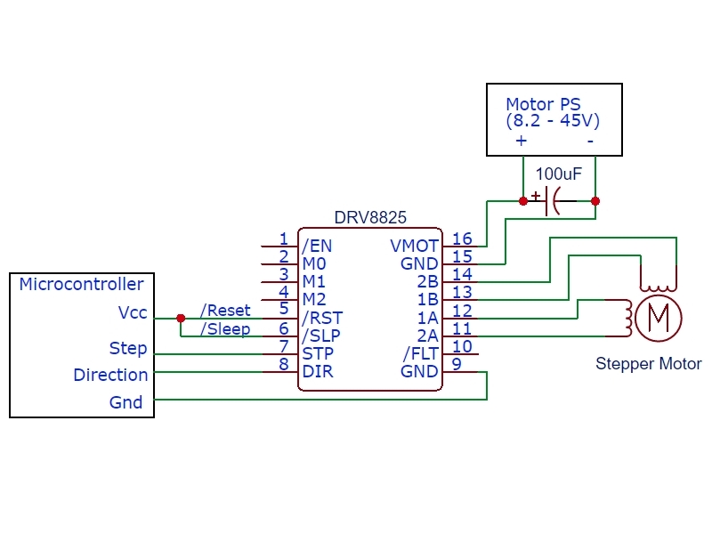
The program below is a simple test program. It uses the module in the minimal hardware mode using just the DIR and STEP pins with the micro-stepping set to the default of full step as shown in the drawing to the right.
It moves the stepper in one direction for 5 rotations, rotates in the reverse direction for 1 rotation and then rotates for one rotation in discrete individual full steps. Ensure that the RST and SLP pins are pulled up to Vcc on the Arduino. Also ensure that the current limiting has been adjusted for the motor you are using.
DRV8825 Stepper Motor Driver Module Program
/*
 * Exercise the DRV8825 Stepper Motor Driver Module
 *
 * This uses the minimal setup configuraiton with DIR connected to pin 8 and
 * STEP connected to pin 9.
 *
 * The /Reset and /Sleep pins need to be pulled up to VCC
 * Step size is left at default of Full Step
 * This uses the BasicStepperDriver.h library which can be downloaded at GitHub
 */
#include <Arduino.h>
#include "BasicStepperDriver.h"

// Motor steps per revolution. Most steppers are 200 steps or 1.8 degrees/step
const int MOTOR_STEPS = 200;
// Set speed of rotation
const int RPM = 120;

// Using default step size. 1=full step, 2=half step, etc.
const int MICROSTEPS = 1;

// Define Arduino pins usedUses default full step
const int DIR_PIN = 8;
const int STEP_PIN = 9;

// Create stepper object in 2-wire basic configuration.
BasicStepperDriver stepper(MOTOR_STEPS, DIR_PIN, STEP_PIN);

//===============================================================================
//  Initialization
//===============================================================================
void setup() {
    stepper.begin(RPM, MICROSTEPS);  // Uses default full step mode
}
//===============================================================================
//  Main
//===============================================================================
void loop() {
   int i;
     for(i=0; i<5; i++) stepper.rotate(360);  // 360 = degrees rotation

    stepper.rotate(-360);   // Rotate once in opposite direction

    for(i=0; i<200; i++){ // Rotate 1 step at a time, pause between steps
      stepper.move(1 * MICROSTEPS); // Steps are full steps
      delay(25);
    }
    delay(1000);
}
BEFORE THEY ARE SHIPPED, THESE MODULES ARE:
- Sample inspected and tested per incoming shipment.
Notes:
- None
TECHNICAL SPECIFICATIONS
| Model | Driver IC | DRV8825 |
| Operating Ratings | ||
| Voltage | 8.2 – 45VDC | |
| Current per phase (Max w/o heatsink) | 1.5A | |
| Current per phase (Max with heatsink) | 2.2A | |
| Microstep resolutions | Full, 1/2, 1/4, 1/8, 1/16, 1/32 | |
| Dimensions | ||
| Driver Board (L x W) | 20 x 15mm (0.8 x 0.6″) | |
| Datasheets | DRV8825 Driver |


