Keszoox
EGS002 Pure Sine Wave Inverter SPWM Driver Board — EG8010 + IR2110, LCD Display
EGS002 Pure Sine Wave Inverter SPWM Driver Board EG8010 + IR2110, LCD Display

Couldn't load pickup availability
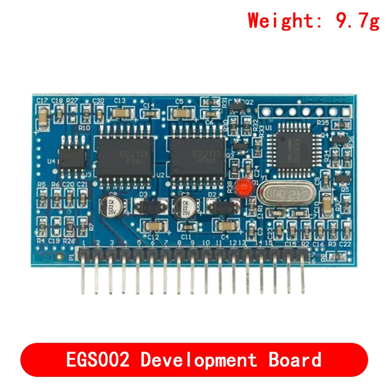
EGS002 — Pure Sine Wave Inverter SPWM Driver Board (EG8010 + IR2110)
The EGS002 is a complete SPWM (Sinusoidal Pulse Width Modulation) driver board for building pure sine wave DC-AC inverters. Based on the EG8010 single-chip pure sine wave inverter controller and IR2110 half-bridge gate drivers, this board generates the SPWM signals needed to drive a full-bridge MOSFET stage — converting DC input to clean 50Hz or 60Hz AC output. An integrated LCD display shows output voltage, frequency, and operating status.
Key Specifications
| Parameter | Value |
|---|---|
| Model Number | EGS002 |
| Controller IC | EG8010 (pure sine wave SPWM generator) |
| Gate Driver IC | IR2110 (half-bridge, ×2) |
| Logic Supply Voltage | 5V DC |
| Output Frequency | 50Hz or 60Hz (selectable) |
| Output Waveform | Pure Sine Wave (SPWM) |
| Display | LCD (output voltage, frequency, status) |
| Protection | Over-temperature, over-current, under-voltage |
| MOSFET Drive | Full-bridge (4× N-channel MOSFETs, external) |
| Origin | Mainland China |
Why Choose EGS002?
- EG8010 SPWM controller — dedicated pure sine wave IC with built-in dead-time control and protection
- IR2110 gate drivers — industry-standard half-bridge drivers for reliable MOSFET switching
- LCD display — real-time monitoring of output voltage and frequency
- 50Hz / 60Hz selectable — compatible with both European and North American AC standards
- Built-in protections — over-temperature, over-current, and under-voltage lockout
- 5V logic supply — easy integration with microcontroller-based control systems
Typical Applications
- DIY pure sine wave inverter — convert 12V/24V/48V DC battery to 110V/220V AC
- Solar power inverter — off-grid solar system AC output stage
- UPS (Uninterruptible Power Supply) — battery backup with clean sine wave output
- Power electronics education — learn SPWM, full-bridge topology, and gate drive design
- Variable frequency drive (VFD) — low-power AC motor speed control
How It Works
The EG8010 generates four SPWM gate signals for a full-bridge topology. The IR2110 gate drivers amplify these signals to drive external N-channel MOSFETs (e.g., IRF3205, IRFP260N). A high-frequency transformer boosts the switched DC to the desired AC voltage, and an LC filter smooths the SPWM output into a clean sine wave. The EGS002 board provides the complete control and drive stage — you add the MOSFETs, transformer, and filter components.
FAQ
Q: Does this board include the MOSFETs and transformer?
A: No. The EGS002 is the driver/control board only. You need to add external N-channel MOSFETs (e.g., 4× IRF3205), a high-frequency transformer, and LC output filter for a complete inverter.
Q: What output voltage can this inverter produce?
A: The output voltage depends on your transformer turns ratio and DC bus voltage. Common configurations produce 110V or 220V AC from 12V, 24V, or 48V DC input.
Q: Is the output a true pure sine wave?
A: Yes. The EG8010 generates SPWM signals that, after LC filtering, produce a pure sine wave with THD typically below 3%.
Package Contents
- 1× EGS002 SPWM Inverter Driver Board (EG8010 + IR2110 + LCD)