


Encoder with Red Illuminated Shaft
Encoder with Red Illuminated Shaft
Compatible JST cables for sensors and modules — secure & reliable. Shop now.

Couldn't load pickup availability

- ★Product Description
- ★About us
- ★Custom cable
Continuously variable position sensor
Description
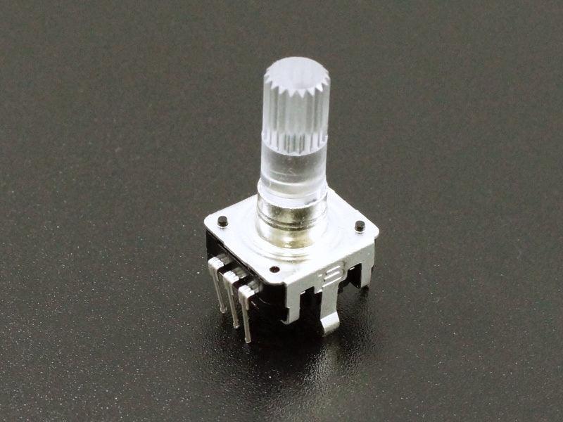
These are high quality Bourns PEL12S-4224S-N1024 12mm vertical mount encoder with a red illuminated knurled shaft. It is a continuously variable position sensor that reports the relative position of the shaft and the direction of rotation. We got a special deal on these and passing them along at a good discount while supplies last.
PACKAGE INCLUDES:
- Bourns PEL12S-4224S-N1024 Encoder with Red Illuminated Shaft
KEY FEATURES OF ENCODER WITH RED ILLUMINATED SHAFT:
- Reports relative position of the shaft
- Reports the direction of rotation of the shaft
- 360 degree continuous rotation
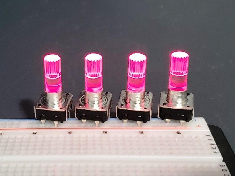
- Shaft can be optionally illuminated with red color
- No pushbutton
- 3.3 and 5V compatible
These encoders, often called rotary encoders, are popular for MIDI sound or similar projects where multiple encoders are used to set various parameters. The optional LED lighting can be used to identify a particular encoder that is active or they can all be lit just for the cool factor.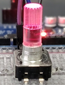
The clear knurled shaft is designed to be rotated without a knob so that the illumination can be seen. If desired a standard potentiometer type of press-on knob can be added to the shaft.
This encoder does not have a built-in pushbutton, so if using for an application such as scrolling through a menu or similar application, a separate button would be needed to select an item.
The rotary encoder is an incremental encoder which means that it outputs a pulse each time that the shaft is rotated one detent (click). The position is kept track of relative to the position that the shaft was in when the controller is first powered on, so it does not have a sense of a specific physical position, but from the software perspective it knows it has gone 5 detents from where it started.
It is continuously variable which means you can continue to spin the shaft around in one direction or the other for as long as you want. It has no mechanical stop.
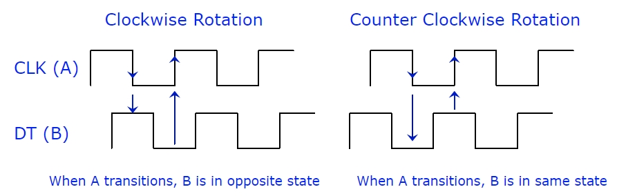
In addition, the encoder can also detect whether the shaft is being turned in the clockwise (CW) or counterclockwise (CCW) direction. Direction of rotation is determined by providing 2 separate pulse outputs that are 90 degrees out of phase with each other. Comparing the 2 outputs to see if they are equal or not when the A changes state tells you if the shaft was rotated CW or CCW as shown in the drawing below.
Shaft Illumination
To illuminate the shaft, 3.3 or 5V is applied across the LED +/- pins with the voltage connected to ‘+’ and ground connected to ‘-‘. Power can come from the power supply if the LED is always on or from a digital pin on an MCU if it is to be software controlled. In either case, a current limiting resistor should be used to avoid possible damage. the maximum rated current for the LED is 25mA, but you will probably want to drive them at a lower current to keep the brightness down. Something in the 220-330 ohm range works pretty well.
Encoder Theory of Operation
The A or ‘CLK’ output is the primary output pulse for determining the amount of rotation. Each time the shaft is rotated by one detent in either direction, the A output goes through one cycle of going HIGH and then LOW. There are 24 detents in a full rotation of the shaft so there would be 24 complete clock cycles.
The B or ‘DT’ (Direction of Travel) output is the same as the A output, but it lags the A by a 90 degree phase shift. This output can be used to determine if the shaft is being rotated in a CW or CCW direction by the state of B when the A changes state. Simply put, if when the A changes state B = A, then the shaft was turned CCW. On the other hand if A changes state and B != A then the shaft was turned CW. Graphic below may help to clarify the logic.
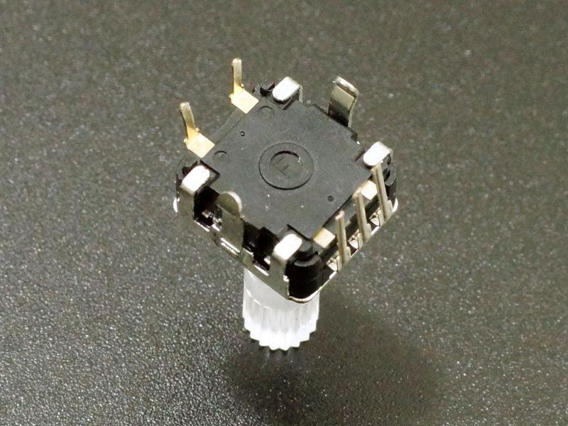
Switch Connections
There area 5-pins on the switch. 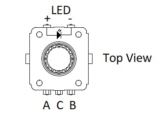
The side with 2 pins is for connections to the LED. Refer to the drawing for the LED connections.
The side with 3 pins is for the encoder output connections
- A = Clock (A) Output Pulse. Connects to digital input on MCU to determine amount of shaft rotation
- C = Ground
- B = DT (B) Output Pulse. Connects to digital input on MCU to determine direction of shaft rotation
OUR EVALUATION RESULTS:
 These are very useful for a number of different types of user input applications. While it does not provide the absolute position of the shaft, it does provide the ability to track how far and which direction the shaft has moved.
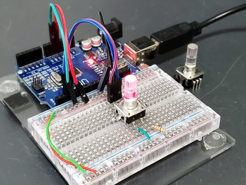
The switch is solderless breadboard compatible if the two mounting tabs are bent outwards or cut off to allow the pins to seat.
While it takes a little software to use, it is fairly easy to implement and it deserves a spot in most hobbyists parts drawer.
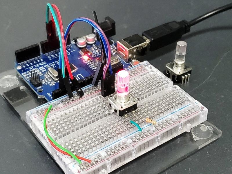
The example program below uses interrupts to provide a high performance interface to the part. It is a pruned down version of a program by Simon Merrett.
To make this software compatible with the Uno, we are using pins 2 and 3 for the interrupt inputs since those are the only interrupt pins on the Uno.
If using multiple encoders, the Mega 2560 has a number of interrupt capable inputs and if using a high performance MCU like the Teensy 4.1, all of the pins can be used for interrupts and it also has the horsepower to do audio synthesis on the fly if that is the application.
If the MCU isn’t doing much else or it is a fast MCU, polling can also be used to read the pins rather than using interrupts, but the chance of missed counts is higher.
Make the following connection:
- A Connect to D2
- C Connect to Ground
- B Connect to D3
The LED can be connected to power and ground via a current limiting resistor if you want to see it glow.
Encoder Test Program.
/*
    This sketch exercises a rotary encoder using interrupts

    Encoder interrupt routine adapted from Simon Merrett's example code
*/

static int pinA = 2; // first hardware interrupt pin is digital pin 2
static int pinB = 3; // second hardware interrupt pin is digital pin 3

volatile byte aFlag = 0; // rising edge on pinA to signal a detent in CW direction
volatile byte bFlag = 0; // rising edge on pinB to signal a detent in CCW direction
volatile byte encoderPos = 0; // current encoder position.
volatile byte oldEncPos = 0; // last encoder position.
  // change encoderPos and oldEncPos to type uint16_t for larger 0-65535 range
volatile byte reading = 0; // store interrupt pins values
//===============================================================================
//  Initialization
//===============================================================================
void setup() {
  pinMode(pinA, INPUT_PULLUP); // set pinA as an input with pullup
  pinMode(pinB, INPUT_PULLUP); // set pinB as an input with pullup
  attachInterrupt(0,PinA,RISING); // set an interrupt on PinA, looking for rising edge
  attachInterrupt(1,PinB,RISING); // set an interrupt on PinB, looking for rising edge
  Serial.begin(115200); // start the serial monitor link
}
//===============================================================================
//  Main
//===============================================================================
void loop(){
  if(oldEncPos != encoderPos) { // Look for encoder position change
    Serial.println(encoderPos); // Print the value if it did change
    oldEncPos = encoderPos;     // Remember the last value
  }
}
//===============================================================================
//  Interrupt Subroutines
//===============================================================================
void PinA(){
  reading = PIND & 0xC; // read all eight Port D pins then strip all but pinA & pinB
  if(reading == B00001100 && aFlag) { // Both pins at detent (HIGH) at pinA rising edge
    encoderPos --; //decrement the encoder's position count
    bFlag = 0; //reset flags for the next turn
    aFlag = 0; //reset flags for the next turn
  }
  else if (reading == B00000100) bFlag = 1; //signal that we're expecting pinB to signal detent
}

void PinB(){
  reading = PIND & 0xC; //read all eight pin Port D pins then strip away all but pinA & pinB
  if (reading == B00001100 && bFlag) { // Both pins at detent (HIGH) at pinB rising edge
    encoderPos ++; //increment the encoder's position count
    bFlag = 0; //reset flags for the next turn
    aFlag = 0; //reset flags for the next turn
  }
  else if (reading == B00001000) aFlag = 1; //signal that we're expecting pinA to signal detent
}
Notes:
- None
Technical Specifications
| Maximum Ratings | ||
| LED Current | Max | 25mA |
| Dimensions | Base | 12.4 x 13.2mm (0.49 x 0.52″) |
| Height including shaft | 24mm (0.95″) | |
| Datasheet | Bourns | PEL12S-4224S-N1024 |


