


LCD1602 16×2 Blue LCD with Keypad Shield
LCD1602 16×2 Blue LCD with Keypad Shield
Compatible JST cables for sensors and modules — secure & reliable. Shop now.

Couldn't load pickup availability

- ★Product Description
- ★About us
- ★Custom cable
16 character x 2 line LCD and keypad in an Arduino shield format.
DESCRIPTION
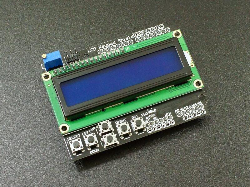
The LCD1602 16×2 Blue LCD with Keypad Shield provides a 16 character x 2 line LCD and keypad in an Arduino shield format for providing a user interface for a project.
PACKAGE INCLUDES:
- LCD1602 16×2 Blue LCD With Keypad Shield
KEY FEATURES OF LCD1602 16×2 BLUE LCD WITH KEYPAD SHIELD:
- 16 character x 2 line Blue LCD
- 5 button keypad + reset
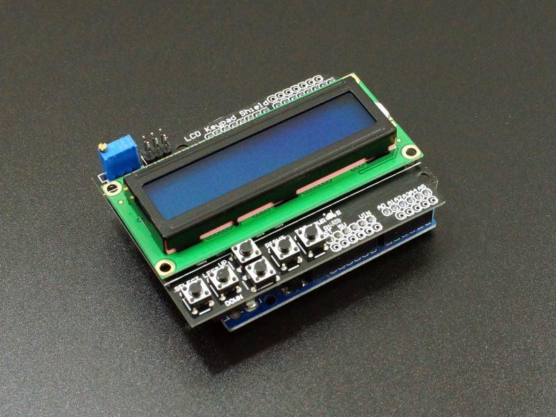
- Fits Arduino Uno, Mega and similar Arduino boards with compatible I/O pin-out
- 5V operation
This shield provides an easy way to implement a user interface suitable for many projects such as having a user navigate through menus on the screen to select functions or setup a program such as for an automated lighting system.
LCD Display
This shield incorporates a 16 character x 2 line blue LCD display. It uses a 4-bit parallel bus to communicate with the MCU. Good library support makes this easy to use as shown in the example program below.
The backlight has a multi-turn potentiometer for adjusting the contrast of the display for best viewing.
Keypad
The module includes a small keypad that has UP/DOWN/LEFT/RIGHT/SELECT buttons. The last button is a remote RESET button.
The buttons (except for reset) all connect to a resistor voltage divider that come into the analog input A0. The output of the voltage divider will vary depending on which button is pushed, so reading the value on analog pin A0 allows you to determine which button was pushed. The example program below shows how this is done in the Read_Buttons() function.
Arduino to Shield Pin Connections
The shield occupies the following pins on the Arduino:
- D4 = LCD DB4
- D5 = LCD DB5
- D6 = LCD DB6
- D7 = LCD DB7
- D8 = RS
- D9 = LCD Enable
- D10 = Backlight Control
- A0 = Analog value of the button pushed
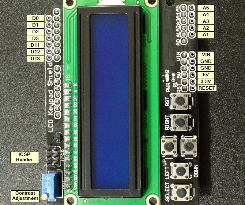
Many of the other pins not used by the LCD or buttons come out to break-out pads on the shield making them available. Wires or headers can be soldered to these pads if desired.
The holes at the top of the module from left to right connect to the following pins on the Arduino which are not used by the LCD.
D13, D12, D11, D3, D2, D1, D0.
The holes along the bottom edge of the board connect to all the pins from RST on the left thru A5 on the right but skips pin A0 which is used by the buttons.
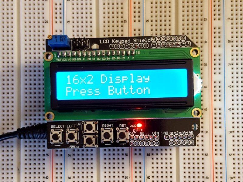
A red LED lights when power is applied.
OUR EVALUATION RESULTS:
Because of the interactivity these provide, they are both fun to play with and useful for more serious projects.
The LCD uses a parallel bus and is somewhat complex to drive directly. Fortunately the LiquidCrystal.h library comes standard with the Arduino IDE that makes it very easy to use the display. There are other libraries available that have enhanced functionality as well. It uses the 4-bit data bus mode to minimize the number of I/O used by the LCD display
Important note about the backlight control on pin 10:
The backlight is enabled when the backlight control on pin 10 is set HIGH. By default this signal is pulled up to 5V on the board, so the backlight is always ON if you do nothing, which is fine for many applications.
If you do want to turn the backlight ON/OFF, you need to define pin 10 as an output and drive it LOW.
The problem is that if you want to then turn the backlight back on by driving pin 10 HIGH, a design error on these boards will cause the pin 10 output of the Arduino to basically be shorted to ground through a transistor which can damage the Arduino. The same thing happens if you try to use PWM to dim the backlight. This problem exists on many boards sold on the internet since they all use a common design.
To safely turn the backlight ON and OFF, use the following method:
- First set pin 10 to LOW once during setup.
- To turn backlight ON, set pin 10 as an INPUT. The pull-up resistor then pulls the signal HIGH to turn on the backlight.
- To turn backlight OFF, set pin 10 as an OUTPUT . Since it was set to LOW originally, as an output it will drive the signal LOW and turn off the backlight.
- Note that using PWM on pin 10 to dim the display still cannot be used.
The program below implements this scheme for safely turning the backlight on/off when the SELECT button is pressed.
The other buttons will report that the button was pushed and will also printout the ADC value that was read which told it which button had been pushed.
The software below uses the Arduino “LiquidCrystal.h” library to test the functionality of the module.
LCD1602 16×2 Blue LCD With Keypad Shield Example Program
/*
 * 16x2 LCD with Keyboard Test
 *
 * Initialize the LCD, then print a simple message to it
 * Respond to button pushes with printouts to the LCD display
 * Select button turns the backlight ON / OFF
 * Need to install library LiquidCrystal.h.
 */
#include <LiquidCrystal.h>

// Define the pins used by the LCD panel.  These are fixed by the shield.
LiquidCrystal lcd(8, 9, 4, 5, 6, 7);

const int BTN_RIGHT = 0;
const int BTN_UP = 1;
const int BTN_DOWN = 2;
const int BTN_LEFT = 3;
const int BTN_SELECT = 4;
const int BTN_NONE = 5;
const int BACKLIGHT_PIN = 10;
const int OFF = 0;
const int ON = 1;

int lcd_key = BTN_NONE;
int adc_key_in = 0;
int backlight_state = ON;
//===============================================================================
//  Initialization
//===============================================================================
void setup()
{
 lcd.begin(16, 2);              // Initialize LCD for 16 character x 2 line operation
 lcd.setCursor(0,0);            // Position cursor to top line, leftmost position
 lcd.print("16x2 Display");     // print a message on the top line

 digitalWrite(BACKLIGHT_PIN,LOW); // We set this pin LOW just once then set to input
}                                 // or output to turn the backlight on/off
//===============================================================================
//  Main
//===============================================================================
void loop()
{
 lcd.setCursor(0,1);        // move cursor to the beginning of the second line
 lcd_key = Read_Buttons();  // read the buttons

 switch (lcd_key)           // Update the display with button pushed
 {                          // and raw ADC data that was read
   case BTN_RIGHT:
     {
     lcd.print("<RIGHT> ADC="); // Print the key that was pressed
     lcd.print(adc_key_in);     // Print raw ADC reading used to determine key pressed
     break;
     }
   case BTN_LEFT:
     {
     lcd.print("<LEFT> ADC=");
     lcd.print(adc_key_in);
     break;
     }
   case BTN_UP:
     {
     lcd.print("<UP> ADC=");
     lcd.print(adc_key_in);
     break;
     }
   case BTN_DOWN:
     {
     lcd.print("<DOWN> ADC=");
     lcd.print(adc_key_in);
     break;
     }
   case BTN_SELECT:   // Toggles backlight ON / OFF
     {
     if (backlight_state == ON) {
      pinMode(BACKLIGHT_PIN,OUTPUT);
      backlight_state = OFF;
     }
     else if (backlight_state == OFF) {
      pinMode(BACKLIGHT_PIN,INPUT);
      backlight_state = ON;
     }
     delay(500);    // This delay is needed to avoid toggling state multiple times
     break;         // with one button press.
     }
     case BTN_NONE:
     {
     lcd.print("Press Button    ");  // The extra spaces serve to clear the display
     break;
     }
 }
}
//===============================================================================
//  Read Buttons - Subroutine to read the ADC and return the button value
//===============================================================================
int Read_Buttons()
{
 adc_key_in = analogRead(0);      // read the value from the sensor
 // The buttons are connected to a voltage divider that feeds into analog input A0.
 // By looking at the voltage level, we can tell which button has been pressed if any.
 // With no button pressed, the voltage will be pulled up to Vcc.
 if (adc_key_in >= 1000) return BTN_NONE; // Most likely result, so it is the first option.
 if (adc_key_in < 50)   return BTN_RIGHT; // Work our way up the voltage ladder and return 1st valid result
 if (adc_key_in < 195)  return BTN_UP;
 if (adc_key_in < 380)  return BTN_DOWN;
 if (adc_key_in < 555)  return BTN_LEFT;
 if (adc_key_in < 790)  return BTN_SELECT;

 return BTN_NONE;  // when all others fail, return this...
}
BEFORE THEY ARE SHIPPED, THESE MODULES ARE:
- Sample inspected and tested per incoming shipment.
Notes:
- Note the correct operation of backlight control as explained above.
TECHNICAL SPECIFICATIONS
| Display | Characters | 16 characters x 2 lines |
| Backlight Color | Blue | |
| Buttons | UP/DOWN/LEFT/RIGHT/SELECT/RESET | |
| Operating Ratings | DC Power Input | 5V |
| Operating Current (Backlight On) | 30mA (typical) | |
| Operating Current (Backlight Off) | 10mA (typical) | |
| Dimensions | ||
| Display Size (with bezel) | 72 x 24mm (2.8″ x .95″) | |
| Shield PCB | 80 x 59mm (3.2 x 2.3″) | |
| Country of Origin | China |


