


LED 7 Color Flashing Module
LED 7 Color Flashing Module
Compatible JST cables for sensors and modules — secure & reliable. Shop now.

Couldn't load pickup availability
Incorporates automatic flashing logic in LED
DESCRIPTION
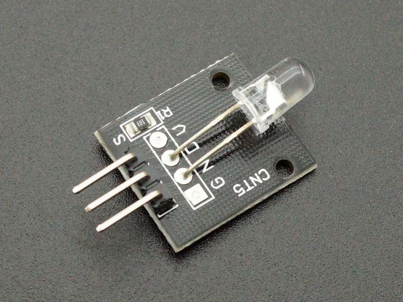
The LED 7 Color Flashing Module incorporates a 5mm tri-color (RGB) LED with red, green and blue LEDs and the logic to cycle through various colors at different speeds all housed in the same package.
PACKAGE INCLUDES:
- LED 7 Color Flashing Module
KEY FEATURES OF LED 7 COLOR FLASHING MODULE:
- RGB (red/green/blue) 5mm LED
- Built-in control logic to cycle through 7 different colors automatically and at various rates
- Operates at 3.3 or 5V
- Requires current limiting resistor
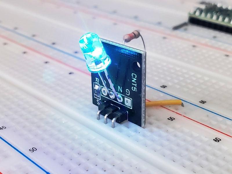
This module provides an eye catching flashing display without a lot of work.
The LED contains logic built-in to automatically flash the LED at different rates while cycling through the 7 possible colors of red, green, blue, yellow, purple, cyan and white by mixing the different LED colors. The LED body is water clear.
Because it has built-in driver, it can be simply wired between 5V and ground to operate (will also work at 3.3V). A current limiting resistor of 220 ohms or so should be placed in series to keep current below 25mA to avoid damage to the LED module. The module can also be controlled by the output pin of an MCU. A current limiting resistor of 220 ohms or greater should be used to protect both the MCU and LED module from excessive current in that case
The module includes a 10K pull-up resistor between the power pin and ground
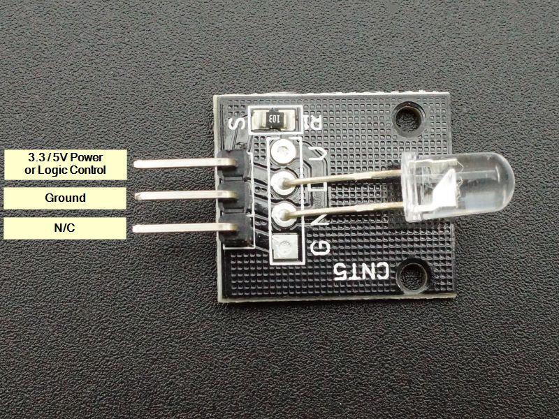
Module Connections
There is a 3-pin header on the assembly. There are a couple of different pin-out labeling in these modules. Refer to the pictures for clarification.
1 x 3 Male Header
- S = Signal input is attached to a digital output pin on MCU via a current limiting resistor or it can be hooked to 3.3 or 5V to have the LED continuously running.
- – / Center pin = Ground
- 3rd pin is not used
OUR EVALUATION RESULTS:
This module is easy to use. The example program below illustrates how to control the LED on/off using an MCU. It is really no different than using a standard LED. Simply hook up a digital output pin via a current limiting resistor to the VCC pin of the module and provide an logic HIGH signal to turn it on and logic LOW to turn it off as shown here. Be sure to also connect the ground pin to the MCU ground. You can also just wire the LED to power and ground using a current limiting resistor if you want it to run continuously.
LED 7 Color Flashing Module Program
/*
7 Color LED module test

Basic code enabling cycling of the module.
*/

int LEDPin = 4; // select a digital pin for the LED
//===============================================================================
//  Initialization
//===============================================================================
void setup()
{
  pinMode (LEDPin, OUTPUT);
  Serial.begin (9600);      // Set output window comm rate
}
//===============================================================================
//  Main
//===============================================================================
void loop()
{
  // Turn the LED on for 10 seconds and then off for 2
  Serial.println ("LED Turned ON");
  digitalWrite (LEDPin, HIGH);
  delay(10000);

  Serial.println ("LED Turned OFF");
  digitalWrite (LEDPin, LOW);
  delay(2000);
}
BEFORE THEY ARE SHIPPED, THESE MODULES ARE:
- Sample inspected and tested per incoming shipment.
Notes:
- None
TECHNICAL SPECIFICATIONS
| Maximum Ratings | ||
| Vcc | 3.3 – 5V | |
| IMax | Maximum Current Draw | 20mA peak |
| Operating Ratings | ||
| Dimensions | L x W (PCB) | 20mm x 15mm (0.75 x 0.60″) |

Blog posts
View all-

Best JST Connector Crimping Tools in 2026: Engi...
Choosing the wrong crimping tool ruins JST connectors and wastes wire. This guide compares the top crimping tools for JST SH, GH, PH, XH, and VH series — including Engineer...
Best JST Connector Crimping Tools in 2026: Engi...
Choosing the wrong crimping tool ruins JST connectors and wastes wire. This guide compares the top crimping tools for JST SH, GH, PH, XH, and VH series — including Engineer...
-

Molex KK 254 vs Mini-Fit Jr. vs Micro-Fit 3.0: ...
Choosing between Molex KK 254, Mini-Fit Jr., and Micro-Fit 3.0? This guide compares pitch, current rating, locking mechanism, wire gauge, and typical applications — with decision tables, part number references,...
Molex KK 254 vs Mini-Fit Jr. vs Micro-Fit 3.0: ...
Choosing between Molex KK 254, Mini-Fit Jr., and Micro-Fit 3.0? This guide compares pitch, current rating, locking mechanism, wire gauge, and typical applications — with decision tables, part number references,...
-

DuPont Connector vs JST PH 2.0: Pinout, Specs &...
Not sure whether to use a DuPont 2.54mm or JST PH 2.0mm connector? This guide compares pitch, locking mechanism, current rating, pinout, and best use cases — so you can...
DuPont Connector vs JST PH 2.0: Pinout, Specs &...
Not sure whether to use a DuPont 2.54mm or JST PH 2.0mm connector? This guide compares pitch, locking mechanism, current rating, pinout, and best use cases — so you can...


