

- ★Product Description
- ★About us
- ★Custom cable
Red, yellow, green, blue and white common cathode with DP
DESCRIPTION
These 3-digit 0.56″ 7-Segment common cathode LED displays include decimal points and are available in red, yellow, green, blue and white.
PACKAGE INCLUDES:
- LED 7-Segment 0.56″ CC 3-Digit
KEY FEATURES OF LED 7-SEGMENT 0.56″ CC 3-DIGIT:
- 3-digit 7-Segment display with common cathode (CC)
- 0.56″ high characters
- Floating decimal point
- 20 mA constant current, 100mA pulsed
- 12-pin package
- Available in red, yellow, green, blue and white colors
Some common uses include displaying voltage and current on a variable power supply, use for a counter display or to keep an electronic score or as a reaction timer display. They are also popular for duplicating the look of some of the displays found in airplanes for creating home-built flight simulators consoles.
Theory of Operation
Each digit of these displays have 7 separate LEDs comprising the 7 segments of the digit plus an 8th LED that functions as a decimal point. The LEDs are labeled segment A thru G and the decimal point is DP.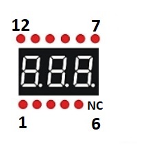
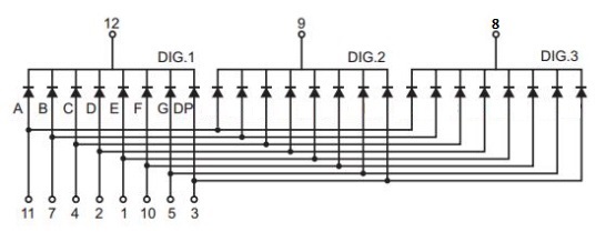
The displays are common cathode (CC) type which means that all 8 of the LEDs in each of the 3 digits have their cathodes tied together and these are pulled to ground to enable that digit. These connections are labeled DIG1 – DIG3 in the drawing.
To light a particular segment, the control (anode) pin for that segment is driven HIGH. These 8 control pins should each have series current limiting resistors to prevent damage to the LED module or the MCU. Instead of the control pins, current limiting resistors can be put on the pins connected to ground so that fewer are needed, but in that case the brightness of the display will vary depending on how many segments are lit at one time so that practice is not really recommended.
The connections for each of the individual segments such a ‘A’ are connected together in all 3 digits, so the displays are designed to be used in a multiplexed fashion unless you want all 3 digits to always show the same number or character which generally isn’t all that useful.
Multiplexing means that the ground connection (DIG1-DIG3 )for each of the displays is enabled sequentially by driving it LOW while the data for that particular digit is driven HIGH to light the desired segments on the 8 LED lines. This is repeated for each of the digits very rapidly so that all of the digits appear to be operating continuously.
The pin-out shown here is as if you are looking at the face of the display.
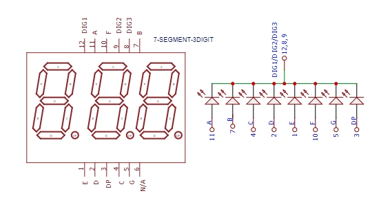
These displays are logic compatible with a max drive current of 20mA and pulsed current up to 100mA. The voltage drop is 2V typical for red and yellow and 3.2V typical for green and blue.
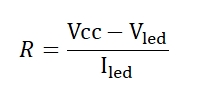
At an operating voltage of 5V, a series current limiting resistor of 150 ohm for red and yellow or 90 ohm for green and blue will provide max brightness if driving these displays in a static mode rather than in a a more typical multiplexing mode.
When you are using displays with multiple digits in a multiplexed mode where each digit is only lit for a portion of the time, the maximum allowable current can be greater than 20mA and can go up to as high as 100 mA. In that case, you generally want to drive the display with more current since each digit in the display is on only a portion of the time and will therefore appear dimmer than if the digit was being driven constantly on.
In most cases, it is preferable to drive these LED displays with a dedicated driver such as the MAX7219 which takes care of all the details of current limiting, multiplexing and driving the display.
OUR EVALUATION RESULTS:
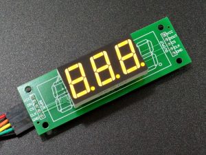
We like 7-Segment LED displays because they display numbers in a very clear format and they are available in a range of sizes. Being encapsulated, they tend to be fairly rugged devices and they have good brightness that is visible even in sunlight. The displays in the pictures are turned down to minimum brightness for the sake of trying to capture the color on camera and are quite bright when driven harder.
The downside to 7-Segment LEDs is that they require 8 drive pins plus 1 per digit in the module. If there are multiple digits, the number of required output pins on a MCU increases quickly and the MCU spends all its time dealing with the display.
Fortunately, there are ICs like the MAX7219 that are made to interface with these modules and make life a whole lot easier. Communication between the MAX7219 and the MCU is made over the SPI bus and the MAX7219 takes care of updating and multiplexing up to 8 of the 7-Segment digits using only 3 pins on the MCU. They also provide on/off and brightness control and multiple ICs can be daisy-chained together for even larger display chains. These ICs are available below in DIP package if you want to roll-your-own circuit.
Notes:
- None
TECHNICAL SPECIFICATIONS
| Display Type | 7-Segment (x 3) | |
| Color | Red/Yellow/Green/Blue | |
| Type | Common Cathode (CC) | |
| Maximum Ratings | ||
| IF | Maximum Constant Forward Current | 20mA per segment |
| Maximum Pulsed Forward Current | 100mA per segment | |
| VF | Maximum Forward Voltage Red / Yellow | 2V (Typical) |
| Maximum Forward Voltage Green / Blue / White | 3.2V (Typical) | |
| Package Type | Encapsulated plastic body, 12-lead, through hole | |
| Dimensions | Character Height | 14.2mm (0.56″) |
| Number of pins | 12-pin. Pin 6 is N/C | |
| Module (L x W x H) | 37.5 x 19 x 8mm (1.47 x 0.75 x 0.32″) | |
| Pin Spacing (row-to-row x pin-to-pin) | 10.16 x 2.54mm (0.4 x 0.1″) |


