


LED RGB 5mm Clear CA (5-Pack)
LED RGB 5mm Clear CA (5-Pack)
Compatible JST cables for sensors and modules — secure & reliable. Shop now.

Couldn't load pickup availability

- ★Product Description
- ★About us
- ★Custom cable
General purpose RGB common anode LEDs that have a water clear lens.
DESCRIPTION
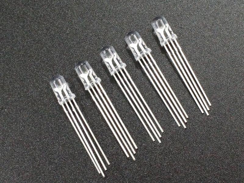
These are general purpose 5mm RGB common anode (CA) LEDs that have a water clear lens. They come in a 5-pack.
PACKAGE INCLUDES:
- Qty 5 – LED RGB 5 mm common anode water clear
KEY FEATURES OF LED RGB 5MM CA WATER CLEAR LENS:
- RGB (Red/Green/Blue) LEDs contained in same package
- Common anode (CA)
- 5mm diameter
- Water clear lens
- 20mA max drive current
- Forward voltage drop of 2.1V red and 2.8V for blue and green
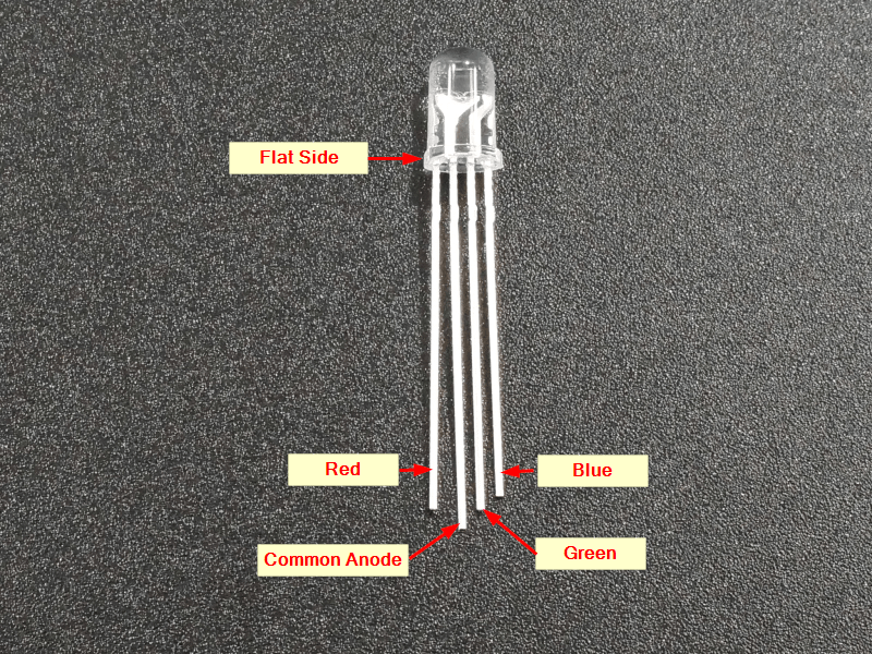
The LED is common anode (CA) which means that all 3 of the LEDs have their anodes tied together. The anode which is the longest lead is connected to Vcc and the red, green and blue LED pins should be connected to digital or PWM output pins that will be driven active LOW to light the LEDs.
Calculating LED Resistor Values
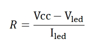
These R/G/B LED pins must have series current limiting resistors to prevent damage to the LED or the MCU that is driving them.
They are logic compatible with a max drive current of 20mA and a typical forward voltage drop of 2.1V for the red and 2.8V for the green and blue LEDs.
At an operating voltage of 5V, series voltage dropping resistors of 150Ω for red and 110Ω for blue and green will provide max brightness or larger resistors of around 220- 470Ω can be used to reduce current at a lower brightness.
OUR EVALUATION RESULTS:
LEDs tend to be fun to play with in general and RGB LEDs are the funnest of all. With regular LEDs, you can turn them on and off, blink them or pulse them rapidly to change the perceived brightness. With RGB LEDs, you can also add playing with color blending which allows you to create pretty much any colors of the rainbow.
The minimal way to drive the LED is by using logic levels to drive the Red/Green/Blue LEDs either individually or several together. Using it this way, you can get 7 possible colors consisting of Red, Green, Blue, Yellow (red and green both on), Purple (red and blue both on), Cyan (blue and green both on) or White (all 3 on). This may be useful for a basic indicator where you want to be able to show several different states using different colors.
More commonly, RGB LEDs are driven using the PWM outputs of a MCU. This allows the brightness of each of the Red/Green/Blue LEDs to be adjusted and therefore it is possible to color mix to get virtually any color you want from the LED.
The example program below uses PWM to show off some of the capability of the RGB LED. First it ramps the brightness of each of the Red, Green and Blue LEDs. Then it arbitrarily mixes the colors of the three LEDs together.
The LED is wired to pins 6, 5 and 3, but any 3 PWM capable pins can be used. Be sure to use a current limiting resistor in series with each of the pins. Refer to the picture for the pin-out of the LED.
LED RGB CA Test Program
/*
RGB LED test

Basic code cycling the colors of an RGB LED.
*/

int const RED_PIN = 6; // select a PWM pin for the red LED
int const BLUE_PIN = 5; // select a PWM pin for the blue LED
int const GREEN_PIN = 3; // select a PWM pin for the green LED
int val=0;
//===============================================================================
//  Initialization
//===============================================================================
void setup()
{
  pinMode (RED_PIN, OUTPUT);
  pinMode (BLUE_PIN, OUTPUT);
  pinMode (GREEN_PIN, OUTPUT);
  analogWrite (RED_PIN,255);
  analogWrite (BLUE_PIN,255);
  analogWrite (GREEN_PIN,255);
}
//===============================================================================
//  Main
//===============================================================================
void loop()
{
  // Cycle each of the Red / Green / Blue LEDs through their brightness range
  // Ramp Red LED up
  for (val = 255; val >= 0; val--)
  {
    analogWrite (RED_PIN, val);
    delay(25);
  }
  analogWrite (RED_PIN,255);
  // Ramp Green LED up
   for (val = 255; val >= 0; val--)
  {
    analogWrite (GREEN_PIN, val);
    delay(25);
  }
  analogWrite (GREEN_PIN,255);
  // Ramp Blue LED up
  for (val = 255; val >= 0; val--)
  {
    analogWrite (BLUE_PIN, val);
    delay(25);
  }
  analogWrite (BLUE_PIN,255);

// Fade Red to Green
 for(int i=255; i>=0; i--) {
    analogWrite(RED_PIN, 255-i);
    analogWrite(GREEN_PIN, i);
    analogWrite(BLUE_PIN, 255);
    delay(25);
  }

  // Fade Green to Blue
  for(int i=255; i>=0; i--) {
    analogWrite(RED_PIN, 255);
    analogWrite(GREEN_PIN, 255-i);
    analogWrite(BLUE_PIN, i);
    delay(25);
  }

  // Fade from Blue to Red
  for(int i=255; i>=0; i--) {
    analogWrite(RED_PIN, i);
    analogWrite(GREEN_PIN, 255);
    analogWrite(BLUE_PIN, 255-i);
    delay(25);
  }
  analogWrite(RED_PIN, 255);
}
Notes:
- None
TECHNICAL SPECIFICATIONS
| Type | RGB | |
| Color | Red / Green / Blue | |
| Lens | Shape | Circular |
| Dimensions | 5 x 8.5mm (0.20 x 0.34″) | |
| Appearance | Clear | |
| Intensity | High Brightness | |
| Viewing Angle | To Half Brightness | 60 Degrees |
| Maximum Ratings | ||
| IF | Maximum Forward Current | 20mA |
| VF | Maximum Forward Voltage | 2.1V Red (Typical) 2.8V Green (Typical) 2.8V Blue (Typical) |
| Package Type | Plastic body, 4-lead, through hole | |
| Mfr | China |


