


LED RGB 5mm Clear Lens Module
LED RGB 5mm Clear Lens Module
Compatible JST cables for sensors and modules — secure & reliable. Shop now.

Couldn't load pickup availability

- ★Product Description
- ★About us
- ★Custom cable
Module incorporates a red, green and blue LED in the same package with built-in current limiting resistors.
DESCRIPTION
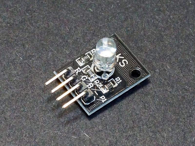
The LED RGB 5mm Module incorporates a red, green and blue LED with clear lens in the same 5mm package and includes built-in current limiting resistors.
PACKAGE INCLUDES:
- LED RGB 5 mm Clear Lens Module
KEY FEATURES OF LED RGB 5 MM CLEAR LENS MODULE:
- RGB (Red/Green/Blue 5 mm LED
- Water clear lens
- Built-in current limiting resistors
The LED is a common cathode type which means all 3 of the LEDs have their cathodes tied together. The cathode is connected to ground and the red, green and blue LED pins should be connected to digital or PWM output pins.
The module has built-in 150 ohm series resistors to limit currents to a safe level, so no additional current limiting resistors are required.
The LED housing is clear, so the LED output is quite bright when viewed straight on unless PWM is used to lower the brightness.
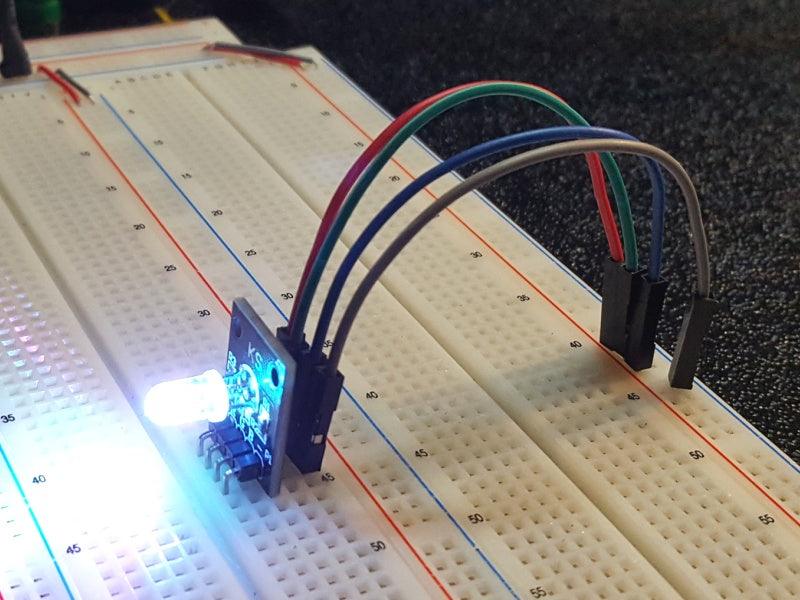
Module Connections
There is a 4-pin header on the assembly for making connections.
1 x 4 Header
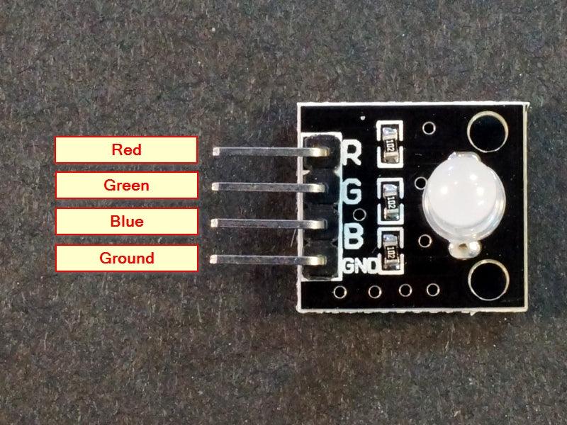
- GND / – = Ground
- G = Green LED anode. Connects to digital output/PWM pin on uC. Active HIGH
- R = Red LED anode. Connects to digital output/PWM pin on uC. Active HIGH
- B = Blue LED anode. Connects to digital output/PWM pin on uC. Active HIGH
OUR EVALUATION RESULTS:
LEDs tend to be fun to play with in general and RGB LEDs are the funnest of all. With regular LEDs, you can turn them on and off, blink them or pulse them rapidly to change the perceived brightness. With RGB LEDs, you can also add playing with color blending which allows you to create pretty much any colors of the rainbow.
The minimal way to drive the LED is by using logic levels to drive the Red/Green/Blue LEDs either individually or several together. Using it this way, you can get 7 possible colors consisting of Red, Green, Blue, Yellow (red and green both on), Purple (red and blue both on), Cyan (blue and green both on) or White (all 3 on). This may be useful for a basic indicator where you want to be able to show several different states using different colors.
More commonly, RGB LEDs are driven using the PWM outputs of a uC. This allows the brightness of each of the Red/Green/Blue LEDs to be adjusted by rapidly pulsing the output and therefore it is possible to color mix to get virtually any color you want from the LED.
The example program below uses PWM to show off some of the capability of the RGB LED. First it ramps the brightness of each of the Red, Green and Blue LEDs. Then it arbitrarily mixes the colors of the three LEDs together.
The LED is wired to pins 2, 3 and 4, but any 3 PWM capable pins can be used
LED RGB 5 mm Module Test Program
/*
RGB LED module test

Basic code cycling the colors of the RGB module.
*/

int redpin = 4; // select a PWM pin for the red LED
int bluepin = 3; // select a PWM pin for the blue LED
int greenpin = 2; // select a PWM pin for the green LED
int val=0;
//===============================================================================
//  Initialization
//===============================================================================
void setup()
{
  pinMode (redpin, OUTPUT);
  pinMode (bluepin, OUTPUT);
  pinMode (greenpin, OUTPUT);
  Serial.begin (9600);      // Set output window comm rate
}

//===============================================================================
//  Main
//===============================================================================
void loop()
{
  // Cycle each of the Red / Green / Blue LEDs through their brightness range
  Serial.println ("Testing Red LED");
  for (val = 0; val <255; val++)
  {
    analogWrite (redpin, val);
    delay(25);
  }
  analogWrite (redpin, 0);

  Serial.println ("Testing Green LED");
   for (val = 0; val <255; val++)
  {
    analogWrite (greenpin, val);
    delay(25);
  }
  analogWrite (greenpin, 0);

  Serial.println ("Testing Blue LED");
  for (val = 0; val <255; val++)
  {
    analogWrite (bluepin, val);
    delay(25);
  }
  analogWrite (bluepin, 0);

  // Do some color mixing by ramping all 3 of the LEDs in different directions at the same time
  Serial.println ("Cycling all 3 LEDs");
  for (val=255; val>0; val--)
  {
    analogWrite (redpin, val);
    analogWrite (bluepin, 255-val);
    analogWrite (greenpin, 128-(val-128));
    delay (25);
  }
  for (val = 0; val <255; val++)
  {
    analogWrite (redpin, val);
    analogWrite (bluepin, 255-val);
    analogWrite (greenpin, 128-(val-128));
    delay (25);
  }
  // Turn LEDs off and repeat the process
  analogWrite (redpin, 0);
  analogWrite (bluepin, 0);
  analogWrite (greenpin, 0);
}
Notes:
- This module is the same or similar to the KY-016.
TECHNICAL SPECIFICATIONS
| Maximum Ratings | ||
| Vcc | 5V | |
| IMax | Maximum Current Draw per LED | 20mA |
| Operating Ratings | ||
| Voltage Drop | Red LED | 1.8-2.4V |
| Green LED | 2.8 – 3.6V | |
| Blue LED | 2.8 – 3.6V | |
| Polarity | Common Cathode | |
| Dimensions | L x W (PCB) | 20 x 15mm (0.75 x 0.60″) |


