


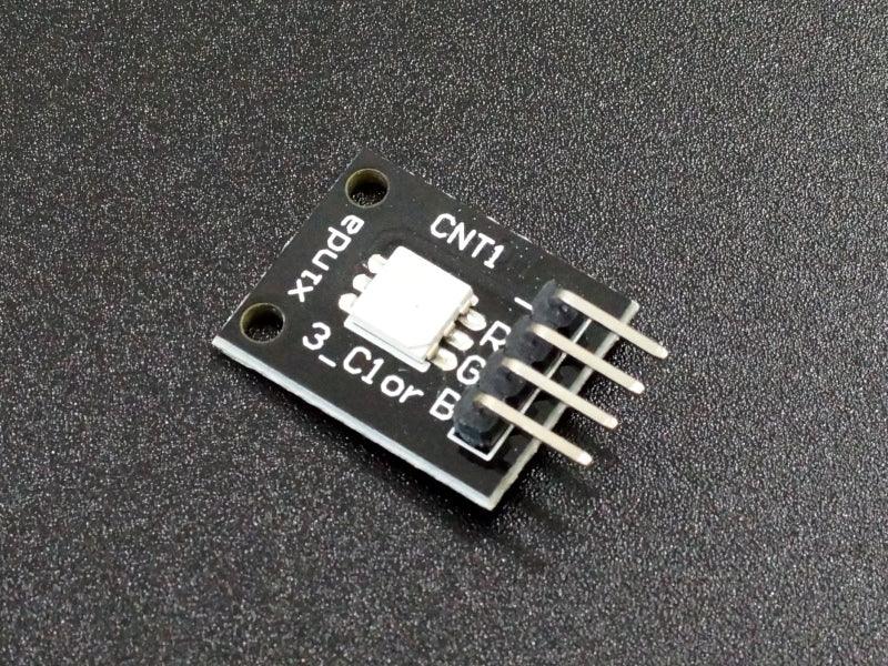
LED RGB SMD Module
LED RGB SMD Module
Compatible JST cables for sensors and modules — secure & reliable. Shop now.

Couldn't load pickup availability

- ★Product Description
- ★About us
- ★Custom cable
Incorporates red, green and blue LED in the same surface mount package.
DESCRIPTION
The LED RGB SMD Module incorporates a red, green and blue LED in the same surface mount package which allows display of full RGB spectrum by mixing the colors.
PACKAGE INCLUDES:
- LED RGB SMD Module
The LED is a common cathode type which means all 3 of the LEDs have their cathodes tied together. The cathode is connected to ground and the red, green and blue LED pins should be connected to digital or PWM output pins with series resistors to limit current to 30mA or less.
Recommended resistor values are around 120 ohms for green and blue and 180 ohms for red. If the microcontroller you are using is limited to 20mA on the output pins, you can increase these values to around 180 ohms and 270 ohms respectively. Higher values can be used but will reduce the brightness.
Driving the outputs HIGH will light the LEDs.
Module Connections
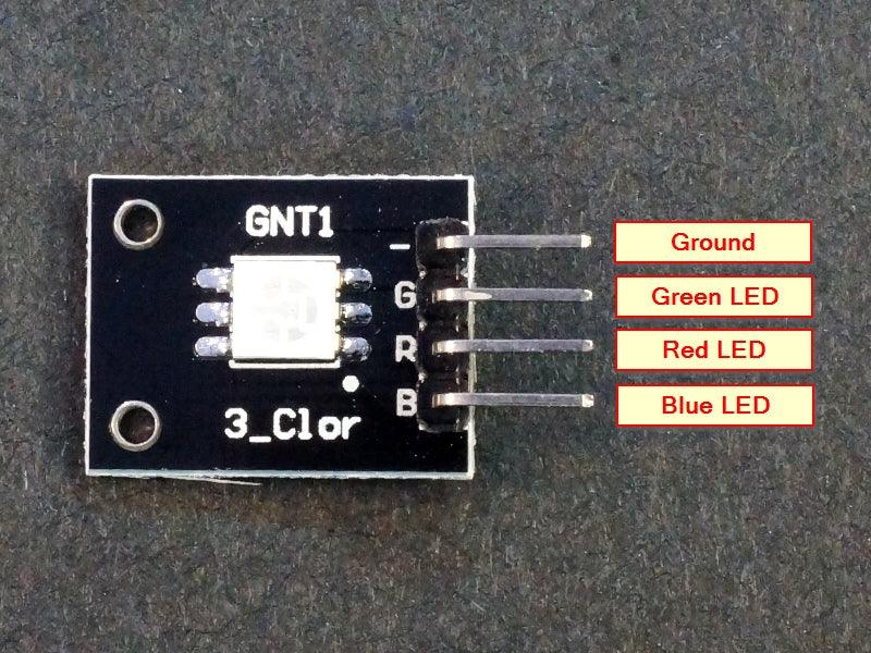
There is a 4-pin header on the assembly for making connections.
1 x 4 Header
- GND / – = Ground
- G = Green LED anode. Connects to digital output/PWM pin on MCU. Active HIGH
- R = Red LED anode. Connects to digital output/PWM pin on MCU. Active HIGH
- B = Blue LED anode. Connects to digital output/PWM pin on MCU. Active HIGH
NOTE: On some modules, we have found the labeling on the R and G channels to be swapped. If you go by our connection diagram, you should be good to go.
OUR EVALUATION RESULTS:
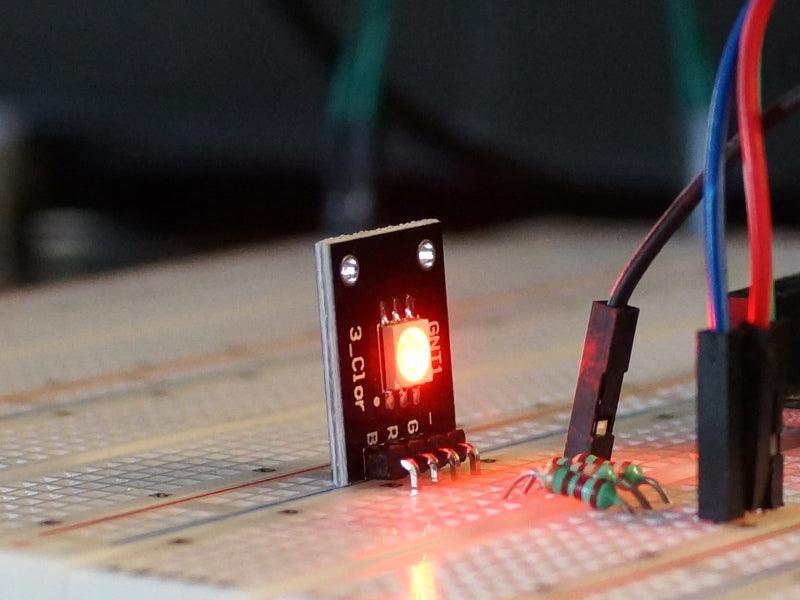
LEDs tend to be fun to play with in general and RGB LEDs are the funnest of all. With regular LEDs, you can turn them on and off, blink them or pulse them rapidly to change the perceived brightness. With RGB LEDs, you can also add playing with color blending which allows you to create pretty much any colors of the rainbow.
The minimal way to drive the LED is by using logic levels to drive the red/green/blue either individually or several together. Using it this way, you can get 7 colors consisting of Red, Green, Blue, Yellow (red and green both on), Purple (red and blue both on), Cyan (blue and green both on) or White (all 3 on). This may be useful for a basic indicator where you want to be able to show several different states using different colors.
More commonly, RGB LEDs are driven using the PWM (analog) outputs of a MCU. This allows the brightness of each of the R/G/B LEDs to be adjusted and therefore it is possible to color mix to get virtually any color you want from the LED.
The example code below uses PWM to show off some of the capability of the RGB LED. Be sure to use current limiting resistors on the PWM outputs to avoid damage.
The LED is wired to pins 2, 3 and 4, but any 3 PWM capable pins can be used.
LED RGB SMD Module Test Program
/*
RGB LED module test

Basic code cycling the colors of the RGB module.

Connect the pins of the LED module to 3 PWM output pins using current
limiting resistors of around 180 to 470 ohms

The pins below can be changed to any 3 PWM capable pins if desired.
*/

int const RED_PIN = 6; // select a PWM pin for the red LED
int const BLUE_PIN = 5; // select a PWM pin for the blue LED
int const GREEN_PIN = 3; // select a PWM pin for the green LED
int val=0;
//===============================================================================
//  Initialization
//===============================================================================
void setup()
{
  pinMode (RED_PIN, OUTPUT);
  pinMode (BLUE_PIN, OUTPUT);
  pinMode (GREEN_PIN, OUTPUT);
  Serial.begin (9600);      // Set output window comm rate
}

//===============================================================================
//  Main
//===============================================================================
void loop()
{
  // Ramp each of the Red / Green / Blue LEDs through their brightness range
  Serial.println ("Testing Red LED");
  for (val = 0; val <255; val++)
  {
    analogWrite (RED_PIN, val);
    delay(25);
  }
  analogWrite (RED_PIN, 0);

  Serial.println ("Testing Green LED");
   for (val = 0; val <255; val++)
  {
    analogWrite (GREEN_PIN, val);
    delay(25);
  }
  analogWrite (GREEN_PIN, 0);

  Serial.println ("Testing Blue LED");
  for (val = 0; val <255; val++)
  {
    analogWrite (BLUE_PIN, val);
    delay(25);
  }
  analogWrite (BLUE_PIN, 0);

  // Do some color mixing by ramping all 3 of the LEDs in different directions at the same time
  Serial.println ("Cycling all 3 LEDs");
  for (val=255; val>0; val--)
  {
    analogWrite (RED_PIN, val);
    analogWrite (BLUE_PIN, 255-val);
    analogWrite (GREEN_PIN, 128-(val-128));
    delay (25);
  }
  for (val = 0; val <255; val++)
  {
    analogWrite (RED_PIN, val);
    analogWrite (BLUE_PIN, 255-val);
    analogWrite (GREEN_PIN, 128-(val-128));
    delay (25);
  }
  // Turn LEDs off an repeat the process
  analogWrite (RED_PIN, 0);
  analogWrite (BLUE_PIN, 0);
  analogWrite (GREEN_PIN, 0);
}
BEFORE THEY ARE SHIPPED, THESE MODULES ARE:
- Sample inspected and tested per incoming shipment.
Notes:
- This module is similar to or the same as the KY-009
TECHNICAL SPECIFICATIONS
| Maximum Ratings | ||
| Vcc | 5V | |
| IMax | Maximum Current Draw per LED | < 30mA |
| Operating Ratings | ||
| Voltage Drop | Red LED | 1.8-2.4V |
| Green LED | 2.8 – 3.6V | |
| Blue LED | 2.8 – 3.6V | |
| Polarity | Common Cathode | |
| Dimensions | L x W (PCB) | 20 x 15mm (0.75 x 0.60″) |


