

- ★Product Description
- ★About us
- ★Custom cable
Provides a 16 GPIO using SPI bus at up to 10MHz.
DESCRIPTION
The MCP23S17 provides a 16-bit general purpose bidirectional I/O port using the SPI bus.
PACKAGE INCLUDES:
- MCP23S17 16-bit I/O Expander with SPI bus
KEY FEATURES OF MCP23S17 16-BIT I/O EXPANDER WITH SPI:
- 16 bidirectional I/O lines
- SPI bus operates up to 10MHz
- 3 address lines for up to 8 devices on same SPI bus
- 2 configurable interrupt outputs
- 25mA per pin / 150mA per package current capability
- 28-pin 0.3″ PDIP package is breadboard friendly
- 3.3 or 5V operation

It’s not unusual to run out of I/O pins on a microcontroller and the MCP23S17 is a way to increase the number of high speed GPIO available and has fairly good library support.
SPI Bus
Since it interfaces using the SPI bus, the MCP23017 uses only 4 pins on the MCU and up to 8 chips can be operated off the same SPI bus for a total of up to 128 I/O lines.
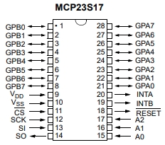
Three address pins (A0-A2) are used for setting the address of the chip. These pins must be tied high or low to set the address and not left floating. If all three pins are tied to ground, the base address is 0x20 and can go up to 0x27 if they are all tied to Vcc. If more than 1 chip is used on an SPI bus, each must be set to a unique address.
The SPI bus can operate at up to 10MHz for very fast manipulation of the I/O lines for high speed applications. Unlike the I2C version of the chip, the maximum speed is the same for both 3.3V and 5V operation.
If an I2C version of this part is preferred, the MCP23017 which is the same chip, but uses the I2C bus can operate at up to 1.7MHz bus speed at 5V or 400kHz bus speed at 3.3V.
I/O Ports
The 16 GPIO lines are configured as two 8-bit ports (PORTA and PORTB). Each pin can also be individually defined as an input or output for complete flexibility.
When pins are configured as inputs, an internal 100K pullup resistor can be enabled which is handy for inputs such as switches that require a pullup to Vcc when the switch is open and pull to ground when pressed. This removes the need to add external pullup resistors in some applications.
Another nice feature is that the input pins can be selectively inverted. For instance, a button press that would normally return a logic LOW can be inverted so it returns a HIGH.
Each GPIO pin can handle up to 25mA, but the total current for all pins must be kept under 150mA. If driving something like 16 LEDs, each LED current needs to be kept down around 9mA if they may all be on at the same time to avoid overheating the chip.
Interrupts
Interrupt capability is a nice feature since the MCU does not have to continuously poll the device looking for any change on the inputs.
Each of the two ports has a configurable interrupt output that can be used independently or the two interrupts can work together. Input pins can be set to interrupt the MCU upon a state change.
Another nice feature is that the interrupt outputs can be configurated as active LOW, active HIGH or OPEN-DRAIN.
Reset
The reset pin is active LOW and must be externally biased. If not using the reset pin, it can be tied to Vcc. It can also be be put under MCU control by connecting it to a digital output pin on the MCU. The pin is normally HIGH and momentarily driven LOW to reset the MCP23S17.
OUR EVALUATION RESULTS:
 These parts are easy to use and have decent library support on most MCU platforms, though not quite as good as the MCP23017 I2C version of the part.
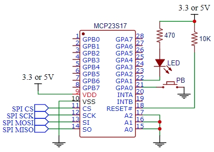
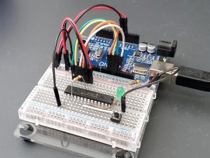
The simple example shown here sets up one pin (GPA0) as an input to detect a button press. A second pin (GPA1) is setup as an output to light an LED while the button is being pressed.
Hookup of the chip is straight forward.
- Pin 9 Vdd – Connect to 3.3V or 5V to match the MCU
- Pin 10 Vss – Connect to ground
- Pin 11 CS – Connect to SPI CS on MCU
- Pin 12 SCK – Connect to SPI SCK on MCU
- Pin 13 SI – Connect to SPI MOSI on MCU
- Pin 14 SO – Connect to SPI MISO on MCU
- Pins 15, 16, 17 A0-A2 – Connect to Ground to set SPI address to 0x20
- Pin 18 RESET – Connect to Vdd using a 10K or so pullup resistor
- Pin 21 GPA0- Connect one side of pushbutton, other side goes to ground
- Pin 22 GPA1 – Connect to LED cathode. Anode of the LED connects to Vdd through 220 to 470 ohm current limit resistor
In this example, we are using the Majenko MCP23S17 library which can be downloaded from GetHub: https://github.com/MajenkoLibraries/MCP23S17
Once the library is downloaded, you can add it using the IDE Include Library / Add .ZIP Library and navigate to where you downloaded it.
Once the program is downloaded to the MCU and running, pressing the pushbutton should cause the LED to light as long as the button is depressed.
An interesting exercise left up to the user is to modify this setup to use interrupts to notify the MCU that the button state has changed rather than constantly polling the MCP23S17 to see what the current state is.
MCP23S17 16-Bit I/O Expander Example Program
/*
 * MCP23S17 Test Program
 *
 * Set one pin as input and detect a button push
 * Set one pin as output and turn on LED when button is pushed
 *
 * Vdd = 3.3V or 5V to match your microcontroller (Vcc)
 *
 * Connect pin #9 (Vdd) of the expander to Vcc (IC power)
 * Connect pin #10 (Vss) of the expander to ground (IC ground)
 * Connect pin #11 (CS) of the expander to SPI CS (Uno 10)
 * Connect pin #12 (SCK) of the expander to SPI SCK (Uno 13)
 * Connect pin #13 (SI)of the expander to SPI MOSI (Uno 11)
 * Connect pin #14 (SO)of the expander to SPI MISO (Uno 12)
 * Connect pins #15, 16 and 17 (A0-2) of the expander to ground
 * Connect pin #18 (RESET) through a ~10kohm resistor to Vcc
 * Connect pin #21 (GPA0) to pushbutton, other side to ground
 * Connect pin #22 (GPA1) to LED cathode, other side to Vcc through 470ohm resistor
 */
#include <SPI.h>          // Arduino SPI library
#include <MCP23S17.h>     // Majenko MCP23S17 Library

const uint8_t chipSelect = 10;
MCP23S17 Bank1(&SPI, chipSelect, 0);    // Uses default address of 0
//===============================================================================
//  Initialization
//===============================================================================
void setup() {
  Bank1.begin();            // use default address 0
  Bank1.pinMode(0, INPUT_PULLUP);  // Switch input with pullup resistor enabled
  Bank1.pinMode(1, OUTPUT); // LED output
}
//===============================================================================
//  Main
//===============================================================================
void loop() {
  int buttonState = 0;

  buttonState = Bank1.digitalRead(0);
  if (buttonState == 0)  // Button is pressed
    Bank1.digitalWrite(1, LOW);  // Turn on LED
  else
    Bank1.digitalWrite(1,HIGH);  // Turn off LED
  delay(100);
}
Notes:
- None
TECHNICAL SPECIFICATIONS
| Operational Ratings | ||
| Vdd | 1.8- 5.5V | |
| Max SPI Clock Speed | Vdd =2.7 to 5.5 | 10MHz |
| Output Current | Per I/O Pin | 25mA |
| Total package output current | 150mA | |
| Package | Footprint | 0.3″ DIP-28 |
| Type | Plastic, thru-hole | |
| Mfr | Microchip | |
| Datasheet | Microchip | MCP23017/MCP23S17 |


