

- ★Product Description
- ★About us
- ★Custom cable
Implements the CAN 2.0B protocol for robust distributed node communication networks.
DESCRIPTION
The MCP2515 CAN Bus Interface Module implements the CAN 2.0B protocol for robust distributed MCU communication networks and includes TJA1050 line driver.
PACKAGE INCLUDES:
- MCP2515 CAN Bus Interface Module
- Jumper for 120 ohm termination resistor
KEY FEATURES OF MCP2515 CAN BUS INTERFACE MODULE:
- Up to 1Mb/s bus speed
- Up to 1000 meter bus length
- Standard and extended data and remote frames
- One-shot mode
- Interrupt output
- SPI interface
- TJA1050 line driver
- 5V Operation
CAN stands for Controller Area Network and it is often thought of as primarily an automotive communication bus since it is the standard for use with automobiles to connect all the electronics and sensors together and is brought out to the outside world via the ODB-II interface.
The CAN bus is in fact a good communication bus for many applications that use multiple distributed MCUs which need to interact with each other such as in factory automation or robotics.
The key features of the CAN bus is that it uses only 2 wires for bus communications and all MCUs connect to these same 2 wires. The CAN bus hardware handles moving the messages through the bus with collision prevention and error correction without requiring any MCU overhead. The messages use message content based IDs rather than MCU IDs, so all CAN bus hardware can access and filter out the messages that are of interest to its associated MCU (node).
Main Features of the CAN Bus
- It is a very robust bus that can handle harsh environmental and electrical noise conditions.
- It implements a complete distributed bus on which over 110 nodes can sit and share information.
- It allows for a centralized system where all nodes can be configured and errors detected from a central point.
- It can tolerate individual node failures without compromising the entire bus.
- Nodes can be added or removed with only minimal system changes required.
- Bus messages can be prioritized into 4 levels based on Message ID and the bus hardware ensure the highest priority messages are transmitted first.
- Messages use a Message ID that indicates what the message is about rather than being addressed to a particular node, so all nodes receive the messages and the CAN hardware filters out the messages that are of interest to its associated node.
- It is low cost to implement and modify since no major wiring or system configuration changes need to be made to add functionality.
The unique message structure facilitates creating a fully distributed system where the nodes act autonomously based on the information available on the bus or it can be used for single master / multiple slave type architectures. With the Message ID concept, modes can be thought of a functional building blocks with defined inputs and outputs in much the same way that software functions or a library in C is used to encapsulate blocks of code functionality.
As an example, a robotic project could have a node that is responsible for proximity and contact detection. The hardware could include an MCU, ultrasonic sensor, motors to move the sensor around and collision switches. The CAN bus hardware on this node could filter through only messages that have to do with proximity and contact such as another node requesting that it conduct a proximity scan. It can put messages on the bus such as sharing the results of the requested scan. The node could also just continually scan its surroundings and put that info on the bus. Any other nodes that care about proximity and scan results can access those messages. A drive motor node for instance may automatically stop the drive motors if a collision switch detection message comes across the bus.
CAN Bus Hardware
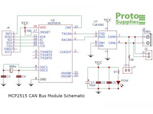
The module includes the MCP2515 CAN Controller IC which handles the logic behind managing the CAN bus and an SPI interface for connecting to its associated MCU. It also includes the TJA1050 CAN Transceiver chip which handles converting the digital data to the differential signaling used on the CAN bus wires.
The physical bus consists of two end nodes which sit at the two ends of the bus. A cable of twisted pair wire which is usually shielded connect the two nodes. For bench-top type use, any 2 wires will work to connect the nodes. As the bus length increases or the environmental electrical noise increases, using twisted pair and adding shielding becomes more important.
The end nodes have a 120 ohm resistor that terminate the two ends of the bus. These are simply added to the circuit using the jumper that is included with the module. For short bus operation, these resistors generally aren’t needed.
Other nodes can be added between the two end nodes. These can be spliced in-line or attached to the main bus using a short stub cable as long as the length is kept under 12″. These additional nodes do not use a 120 ohm termination resistor.

Typical CAN Bus Arrangement
The data rate is programmable and the slower the data rate, the longer the bus can be extended. At the maximum data rate of 1Mbit/s the maximum bus length is 40 meters. At 125kbit/s it can reach up to 500 meters. Slower speeds can go further still.
The CAN Bus hardware handles the basic low level message handling with a couple of transmit and receive buffers, bus handshaking, collision detection and CRC error detection. This hardware level also has the ability to filter incoming messages based on Message ID and only pass messages of interest through to the associated MCU. On outgoing messages, it can prioritize the messages and ensure that the highest priority messages are put on the bus in front of low priority messages.
As noted before, the CAN Bus is fairly unique because it uses a message based protocol. Usually when sending messages on a distributed system, you send a message from point A to point B. With the CAN Bus, nodes are not given IDs, so the messages are not address from or to a particular node. Rather the message has a CAN ID that indicates what the message relates to and all other nodes receive that message and each node uses filtering to determine which messages are of interest to it.
The CAN ID is 11 or 29 bits in length. The data that the message contains can be anywhere between 0 and 8 byes in length.
CAN Bus Software
Using the CAN Bus requires using a library to handle and hide all the messy details involved with using the bus. Fortunately many libraries are available and we use one of the stock ones that come with the Arduino IDE in our example below.
Incoming messages can be polled for in a loop or the module can provide an interrupt output which indicates that a message of interest is available because it met one of the filter criteria that had been set.
With a basic CAN Bus library installed, the bus can be used to create a distributed network of Arduino or other MCUs for a custom application.
If your end goal is to connect to something like the ODB-II CAN Bus on your automobile, you will need a library that implements the high level protocol used for that specific application.
Module Connections
The main uC connection is via a 7-pin male header. The CAN bus can be connected using either a 2-pos screw terminal or a 2-pin male header.
1 x 7 Header (J4)
- INT = Interrupt output
- SCK = SPI SCK – Connects to same on MCU
- SI = SPI MOSI – Connects to same on MCU
- SO = SPI MISO – Connects to same on MCU
- GND = Ground – Connect to MCU ground
- Vcc = 5V
1 x 2 Header (J3)
- H = CAN Bus H connection
- L = CAN Bus L connection
1 x 2 Screw Terminal (J2)
- H = CAN Bus H connection
- L = CAN Bus L connection
1 x 2 Header (J1)
- Add jumper to include 120 ohm termination resistor at each end of the CAN Bus
- Remove jumper to remove 120 ohm termination resistor from nodes in middle of the CAN Bus
The module has 4 holes for mounting.
OUR EVALUATION RESULTS:
These modules have good build quality and have worked well in our testing.
The CAN Bus is an underutilized bus and well worth exploring in the context of a distributed MCU system as it allows more of the system architecture to be moved to the software side of the equation which increases flexibility. You don’t see cars having to have their CAN bus rewired every time some module is changed to add or remove a feature.
The software below uses the mcp_can.h library which is downloadable from the Arduino IDE. It also uses the SPI.h library to connect to the SPI interface on the module.
The software is broken into separate transmit and receive programs and illustrates basic setup and message passing between two CAN modules. They are based loosely on the library sample Send / Receive programs. There are other sample programs that come with the library that illustrate some of the more advanced features of the CAN Bus.
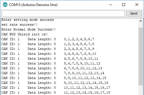
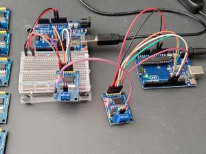
You will need two Arduino boards of any type or other MCU and two of these MCP2515 CAN modules to construct a basic setup to get started with. The software is simplistic and the transmit program just passes some data to the bus every 1/2 second and and the receiver program uses polling to determine if there is a message available and displays it in the Serial Monitor window which will look something like this. It displays the CAN ID, number of data bytes sent and then displays the data bytes that were transmitted. In our case, we are just incrementing the data bytes in each message that is sent.
Hooking things up:
Connect the SPI interface to each module. The pin locations will vary depending on the boards you are using, but these shown below are the most common.
- For Uno and most other Arduino boards
- SCK D13 to module SCK
- MISO D12 to module SO
- MOSI D11 to module SI
- For Mega 2560
- SCK D52 to module SCK
- MISO D50 to module SO
- MOSI D51 to module SI
Connect CS (chip select) to D10 but this can be changed to any available digital pin in the programs below by changing this statement: MCP_CAN CAN(10)
Connect Vcc and Ground pins on the module to 5V and ground on the MCU.
Connect the CAN bus straight through, so CAN L connects to CAN L and CAN H to CAN H. Also ensure the 120 ohm resistor jumper is in place on both modules, though this doesn’t generally matter for short bench-top setups.
Download the software into the two MCUs and open the Serial Monitor window on the receive node. Ensure that the baud rate is set to 115200.
MCP2515 CAN Bus Module Transmit Program
/*
  Exercise the MCP2515 CAN Bus Module (Sending Module Code)
  Requires 2 Arduino compatible boards and 2 CAN bus modules to create a link
  Module connects to power/ground and SPI bus.  Pin 10 used for CS.
*/

#include <SPI.h>          // SPI is used to talk to the CAN Controller
#include <mcp_can.h>      // CAN Bus library

MCP_CAN CAN(10);          // Set CAN Bus Chip Select to pin 10
byte data[8] = {0, 0, 0, 0, 0, 0, 0, 0};  // Msg 8 byte data
//===============================================================================
//  Initialization
//===============================================================================
void setup()
{
  Serial.begin(115200);   // Initialize communication with Serial monitor

 Serial.println("CAN transmitter test");
   // Initialize MCP2515 running at 16MHz with a baudrate of 500kb/s
  if(CAN.begin(MCP_ANY, CAN_500KBPS, MCP_16MHZ) == CAN_OK)
    Serial.println("MCP2515 Initialized Successfully!");
  else
    Serial.println("Error Initializing MCP2515...");

  CAN.setMode(MCP_NORMAL);   // Normal mode to allow messages to be transmitted
}

//===============================================================================
//  Main
//===============================================================================
void loop()
{
  for (byte val = 0; val <= 247; val++) {
    //Assign some changing dummy values for the 8 bytes of data
    data[0] = val;
    data[1] = val + 1;
    data[2] = val + 2;
    data[3] = val + 3;
    data[4] = val + 4;
    data[5] = val + 5;
    data[6] = val + 6;
    data[7]= val + 7;
  //CAN.sendMsgBuf(msg ID, standard frame, #of data bytes, data array);
  byte sndStat = CAN.sendMsgBuf(0x01, 0, 8, data);
  if(sndStat == CAN_OK){
    Serial.println("Message Sent Successfully!");
  } else {
    Serial.println("Error Sending Message...");
  }
  delay(500);
  }
}
MCP2515 CAN Bus Module Receive Program
/*
  Exercise the MCP2515 CAN Bus Module (Receiving Module Code)
  Requires 2 Arduino boards and 2 CAN bus modules to create a link
  Module connects to power/ground and SPI bus.  Pin 10 used for CS.
*/

#include <SPI.h>          //SPI is used to talk to the CAN Controller
#include <mcp_can.h>

MCP_CAN CAN(10);          //set CAN Bus Chip Select to pin 10

unsigned char len = 0;    // length of received buffer
unsigned char buf[8];     // Buffer to hold up to 8 bytes of data
long unsigned int canID;       // Can message ID
//===============================================================================
//  Initialization
//===============================================================================
void setup()
{
  Serial.begin(115200);   // Initialize communication with Serial monitor

  Serial.println("CAN receiver test");
 // Initialize MCP2515 running at 16MHz with a baudrate of 500kb/s
  if(CAN.begin(MCP_ANY, CAN_500KBPS, MCP_16MHZ) == CAN_OK)
    Serial.println("MCP2515 Initialized Successfully!");
  else
    Serial.println("Error Initializing MCP2515...");

  CAN.setMode(MCP_NORMAL);   // Normal mode to allow messages to be received
}

//===============================================================================
//  Main
//===============================================================================
void loop()
{
    if(CAN_MSGAVAIL == CAN.checkReceive())    //check if data is coming in
    {
        CAN.readMsgBuf(&canID, &len, buf);    // Read data,  len: data length, buf: data buffer

        Serial.print("CAN ID: ");
        Serial.print(canID, HEX);     // print the CAN ID in HEX

        Serial.print("    Data Length: "); // Print the length of the received data
        Serial.print(len);
        Serial.print("    ");

        for(int i = 0; i<len; i++)    //loop on the incoming data to print each byte
        {
            Serial.print(buf[i]);
            if(i<len-1) Serial.print(",");  // Separate the numbers for readability
        }
        Serial.println();
    }
}
BEFORE THEY ARE SHIPPED, THESE MODULES ARE:
- Sample inspected and tested per incoming shipment
Notes:
- None
TECHNICAL SPECIFICATIONS
| Operating Ratings | ||
| Vcc | Range based on TJA1050 requirements | 4.75 to 5.25V |
| Temperature | Range | -40 to 125°C |
| Parametrics | Tx Buffers | 3 |
| Rx Buffers | 2 | |
| Msg Filters | 6 | |
| Masks | 2 | |
| Interrupt Outputs | 1 | |
| Crystal Frequency | 8Mhz | |
| Dimensions | L x W (PCB) | 41 x 39mm (1.6 x 1.5″) |
| Country of Origin | China | |
| Datasheets | Microchip | MCP2515 |
| NXP / Phlips | TJA1050 |


