


MCP2562FD High-Speed CAN Bus Transceiver
MCP2562FD High-Speed CAN Bus Transceiver
Compatible JST cables for sensors and modules — secure & reliable. Shop now.

Couldn't load pickup availability

- ★Product Description
- ★About us
- ★Custom cable
Provides interface between bus controller and physical CAN bus
DESCRIPTION
The MCP2562FD is a high-speed CAN transceiver that operates at up to 8Mbps. It provides the interface between a CAN protocol controller and the physical 2-wire CAN bus. It has the same features as the MCP2562 but supports higher bus speeds required for CAN FD.
PACKAGE INCLUDES:
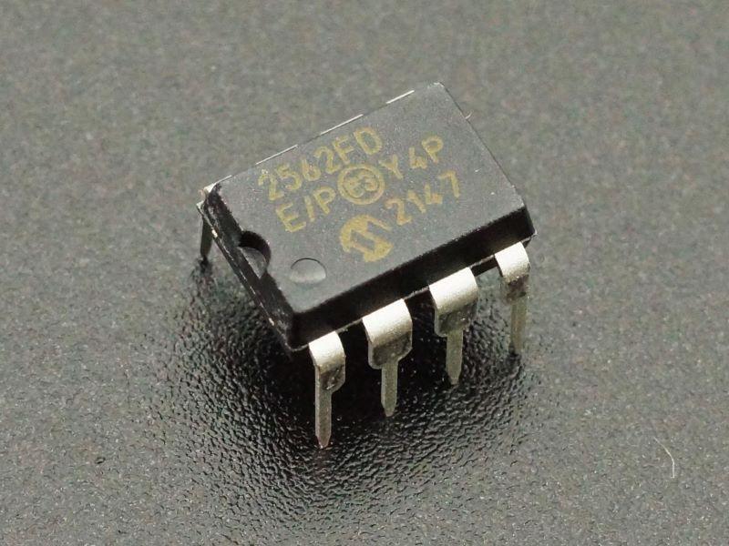
- MCP2562FD-E/P CAN Bus Transceiver DIP IC
KEY FEATURES OF MCP2562FD:
- Up to 8Mb/s bus speed
- Up to 112 nodes
- 5V Operation
- 3.3 and 5V logic compatible
CAN stands for Controller Area Network and it is often thought of as primarily an automotive communication bus since it is the standard for use with automobiles to connect all the electronics and sensors together and is brought out to the outside world via the ODB-II interface.
The CAN bus is in fact a good communication bus for many applications that use multiple distributed MCUs which need to interact with each other such as in factory automation or robotics.
The key features of the CAN bus is that it uses only 2 wires for bus communications and all MCUs connect to these same 2 wires.
This IC is used to provide the interface for connecting a built-in CAN bus controller as found in some of the more advanced MCUs like the Teensy 4.1, to the physical differential bus lines that connect the different MCUs on the bus.
CAN Bus Hardware Connections
The physical bus consists of two end nodes which sit at the two ends of the bus. A cable of twisted pair wire which is usually shielded connect the two nodes. For bench-top type use, any 2 wires will work to connect the nodes. As the bus length increases or the environmental electrical noise increases, using twisted pair and adding shielding becomes more important.
The end nodes have a 120 ohm resistor that terminate the two ends of the bus.
Other nodes can be added between the two end nodes. These can be spliced in-line or attached to the main bus using a short stub cable as long as the length is kept under 12″. These additional nodes do not use a 120 ohm termination resistor.
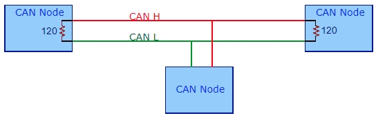
Typical CAN Bus Arrangement
IC Connections
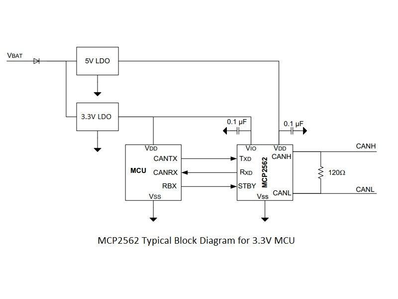
 Connections to this IC are pretty straightforward. The IC is powered from 5V on the Vdd pin and ground on the Vss pin.
The voltage of the I/O is controlled by the voltage applied to the Vio pin. If this is being used with a 5V MCU, the Vio can be connected to Vdd. If it is being used with a 3.3V MCU, Vio should be connected to 3.3V.
The MCU connects to the Txd / Rxd pins. Txd connects to the transmit data output of the CAN bus controller while Rxd connects to the receive data input on the CAN bus controller.
The physical CAN bus connects to the CANH / CANL pins. CANH output drives the high-side of the CAN differential bus lines. The CANL output drives the low-side. CANH is connected to other CANH and CANL are connected to other CANL. The transceivers at the two ends of the physical bus should have 120 ohm load resistors placed between CANH and CANL.
Standby is internally pulled HIGH and is enabled by default. Standby puts the IC into a low power partial sleep mode. For normal operation, pull the STBY pin LOW or tie to ground if standby mode is not going to be used.
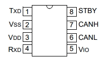
- Txd = Transmit Data Input from MCU
- Vss = Ground
- Vdd = Supply Voltage (4.5 – 5.5V)
- Rxd = Receive Data Out to MCU
- Vio = Digital I/O Supply Pin. For 3.3V MCU, connect to 3.3V. For 5V MCU connect to 5V
- CANH = CAN Bus H connection. CANH connects to CANH on other transceivers
- CANL = CAN Bus L connection. CANL connects to CANL on other transceivers
- STBY = Standby Mode Input. Pull LOW to disable
OUR EVALUATION RESULTS:
The CAN Bus is an underutilized bus and well worth exploring in the context of a distributed MCU system as it allows more of the system architecture to be moved to the software side of the equation which increases flexibility. You don’t see cars having to have their CAN bus rewired every time some module is changed to add or remove a feature. It is also very robust in order to survive the harsh automotive environment.
These chips work well for adding the final link between the CAN bus controllers that are often present on more advanced MCUs and the physical bus wires.
Notes:
- None
TECHNICAL SPECIFICATIONS
| Operating Ratings | ||
| Vdd | Range | 4.5V to 5.5V |
| Vio | Range | 1.8V to 5.5V |
| Icc | Typical recessive current | 5mA |
| Typical dominant current | 45mA | |
| Typical standby current | 5uA | |
| Datasheets | Microchip | MCP2562FD |


