

- ★Product Description
- ★About us
- ★Custom cable
Wireless technology commonly embedded into key cards..
DESCRIPTION
MFRC522 RFID is the wireless technology commonly embedded into key cards to give access to something like a locked door by holding the card up to a reader. It is also used in many other applications such as inventory control, animal identification and casino tracking and billing of customers. MFRC522 is the RFID technology from NXP Semiconductors.
PACKAGE INCLUDES:
- MFRC522 RFID Reader Module
- RFID Key Card
- RFID Key Ring
- Straight and right-angle male headers
KEY FEATURES OF MFRC522 RFID READER, KEY CARD AND KEY CHAIN:
- MFRC522 Reader supports MIFARE Mini, 1K, 4K, Ultralight, DESFire EV1 and Plus RF protocols
- Ships with blank MIFAR 1K Key Card and Key Chain
- Conforms to parts of the ISO/IEC 14443 Type A 13.56MHz smart card standard
- 13.56MHz operation
- SPI Interface
- 3.3V operation
RFID stands for ‘Radio Frequency Identification’. This kit is ideal for becoming familiar with RFID technology and it is suitable for implementing a complete basic RFID application.
The RFID Reader which is the circuit board contains the MFRC522 Contactless Reader Integrated Circuit. The Reader can both read from and write to key cards or key rings. The Readers are referred to as the Proximity Coupling Device (PCD).
The PCD board includes an RF antenna which is made from PCB traces which is why it is as big as it is. The RF antenna creates a 13.56MHz electromagnetic field that is used to both power and communicate with a key card or key ring when it comes within about 1 inch distance. The PCD can read cards placed on either side of the PCB.
The key card and key ring that comes with the kit each contains a small embedded RFID chip. These are referred to as a Proximity Integrated Circuit Card (PICC). These PICC devices do not contain a battery, but rather the chip inside is powered by the RF energy of the PCD when it comes into close proximity. Once the PICC chip is activated, data can be read from or written to the chip. Every RFID chip has a unique serial number that identifies that particular key card, key ring or whatever else the RFID chip is embedded in.
The MIFARE Classic 1K devices included in this kit provide 1024 bytes of data storage. The first 16 bytes are reserved for the serial number of the card and mfg data. The remaining memory is divided into 16 sectors. Each sector can be protected by two different keys. The first 16 bytes of each sector is reserved for the access keys and conditions.
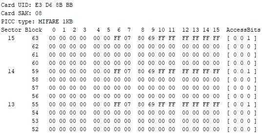
This shows the typical header info and the content of the last 3 memory sectors of a typical PICC device as reported by the software program down below.
Card UID: Stands for Card Unique ID and is the unique serial number assigned to that device
Card SAK: Stands for Select Acknowledge. This identifies the particular chip type and its level of compliance to the ISO/IEC 18092 Protocol standard. These PICCs will all report as 0x08
PICC Type: Identifies the particular technology being used. In this case it is the MIFARE 1KB Classic
Sector Block: The 16 sector blocks follow. The first line of each sector includes the keys for that sector which are set to all 0xFFs from the factory. The next 3 lines of each sector are the user data bytes are all set to their default 0x00 from the factory. These blocks can be used to write data to memory and read it back out later. For instance in some cases it may be desirable to increment a number on the card each time the card is used or to add a dollar amount.
Module Connections
The main connections are via an 8-pin male header. Both straight and right angle headers are included in the kit. The header can be soldered to either side of the board or wires can be used for attachment.
1 x 8 Header
- 3.3V = 3.3V power – Usually powered off 3.3V output of MCU
- RST = Reset – Under MCU control
- GND = Ground – must be common with the MCU
- IRQ = Interrupt Request Output. Not typically used.
- MISO = SPI MISO – Connect to same on MCU
- MOSI = SPI MOSI – Connect to same on MCU
- SCK = SPI SCK – Connect to same on MCU
- SDA = SPI SDA / SS – Connect to same on MCU
The module has 4 holes for mounting.
OUR EVALUATION RESULTS:
These modules have good build quality and have worked well in our testing. Pair it with one of our electric door solenoids below and you are half way to implementing a key card entry setup.
Take note that the RFC522 Reader operates at 3.3V only. In our example below we are powering it off the Uno 3.3V output. When using the device with a 5V MCU, the SPI interface signals should be level shifted to avoid possible damage. In our testing, we have operated these modules off 5V SPI signals without any issues noted, but a level translator is recommended to stay within the published chip specs, especially if putting into permanent operation. Our TXS0108E 8-Ch Logic Level Translator shown below works well for this purpose.
MFRC522 is an older RFID technology that is easy to use but it is not impervious to hacking. If you need high security such as in some commercial applications, one of the newer standards such as MIFARE Plus or MiFare DESFire should be used. With the higher security comes a higher level of difficulty in using those parts which is what makes these parts ideal for getting started with RFID technology and implementing lower security applications.
In our example we are using the MFRC522 library that can be downloaded from the Arduino IDE. The PCD Reader itself can support the other standards, but the library used here implements support for the RC522 only.
The program shown here is taken from the DumpInfo example program that comes with the library and shows how easy it is to get basically up and running with reading a card. We use this program to test that the hardware and cards work before shipment.
The library also comes with a number of example programs that illustrate actual applications in considerable detail that can help jump-start a more full featured application.
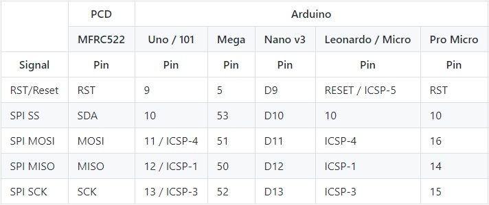
Pins RST and SS_PIN are connected to D9 and D10 respectively. This are software configurable and can be changes as needed. The table below shows the typical connections for different Arduino MCU.

Once everything is hooked up and the program is downloaded and running, open the Serial Monitor window to see the output. Note that we are using a baud rate of 115200 so set the Serial Monitor window accordingly. We are using a higher speed link so that we can download the data faster to the window.
Hold the key card up near the antenna of the Reader and you should see the content of the card being downloaded. If you move the card away during the middle of the data download, you will get a ‘PCD_Authenticate() Failed: error. If that happens, just move the card back near the antenna and the data download will be restarted.
MFRC522 RFID Test Program
/*
   MRFC522 RFID Tag Test Program

  Simple program to scan the card or keychain and return the header info
  and any data loaded on the card.  This is a version of the sample program
  'DumpInfo' that comes with the MFRC522 library

   Uses MFRC522.h Library which can be downloaded via the Arduino IDE
*/
#include <MFRC522.h>      // Include the RC522 Library
#include <SPI.h>          // Include SPI Library

#define RST_PIN 9          // Configurable pins for SPI bus
#define SS_PIN  10

MFRC522 mfrc522(SS_PIN, RST_PIN);  // Create MFRC522 instance

//===============================================================================
//  Initialization
//===============================================================================
void setup() {
  Serial.begin(115200);    // Initialize serial comm
  while (!Serial);       // Do nothing if no serial port is opened (added for Arduinos based on ATMEGA32U4)
  SPI.begin();          // Init SPI bus
  mfrc522.PCD_Init();   // Init MFRC522
  mfrc522.PCD_DumpVersionToSerial();  // Show details of PCD - MFRC522 Card Reader details
  Serial.println(F("Scan PICC to see UID, SAK, type, and data blocks..."));
}
//===============================================================================
//  Main
//===============================================================================
void loop() {

  // Look for new cards
  if ( ! mfrc522.PICC_IsNewCardPresent()) {
    return;
  }

  // Select one of the cards
  if ( ! mfrc522.PICC_ReadCardSerial()) {
    return;
  }

  // Dump debug info about the card; PICC_HaltA() is automatically called
  mfrc522.PICC_DumpToSerial(&(mfrc522.uid));
}
BEFORE THEY ARE SHIPPED, THESE MODULES ARE:
- Sample inspected and tested per incoming shipment.
Notes:
- You can’t use to scan your dog. Those RFI tags use 125kHz for scanning.
TECHNICAL SPECIFICATIONS
| Operating Ratings | ||
| Vcc | 2.5 to 3.6V | |
| Imax | Reader Module | 23mA (measured) |
| Data Rates | Maximum | 848 kBd |
| Detection Distance | Maximum | 25mm (typical measured) |
| Subcarrier Frequency | 13.56MHz | |
| Dimensions | L x W (PCB) | 60 x 40mm (2.4 x 1.6″) |
| Country of Origin | China | |
| Datasheets | NXP | MFRC522 |
FURTHER READING


