

- ★Product Description
- ★About us
- ★Custom cable
Non-inverting logic compatible driver capable of up to 9A peak and 2A continuous output.
DESCRIPTION
The MIC4422 MOSFET Driver is a non-inverting logic compatible driver capable of up to 9A peak and 2A continuous output.
PACKAGE INCLUDES:
- MIC4422 MOSFET Driver
KEY FEATURES OF MIC4422 MOSFET DRIVER:
- Can source up to 9A peak and 2A continuous current
- Fast switching speeds of 25nS
- Input hysteresis for clean switching
- Non-inverting output
- 4.5 to 18V operating range
- 3.3 and 5V logic compatible
If you have a uC and you want to control some serious power with it like large motors, that typically means hooking up a large power MOSFET to one of its logic output pins. If you have a logic  level compatible MOSFET like our STP40NF10L, you may be all set. But if you have a more typical MOSFET which has higher voltage drive requirements than the uC can provide or you need very fast switching times for efficiency, this MIC4422 MOSFET driver may be just what you need.
The MIC4422 is a fast non-inverting low-side driver that is logic compatible on the input and capable of up to 9A (peak) on its output and can drive the largest or multiple power MOSFETs without breaking a sweat. It is also a fairly flexible part that can be used in a number of different driver type applications.
If you are using the MOSFET to occasionally turn something on or off, achieving maximum efficiency may not be all that important, but for fast switching in an application like DC-DC conversion or motor speed control, getting the MOSFETs through their inefficient linear region as quickly as possible can be important. The high current and fast switching capability of these devices handles large capacitive loads to ensure that happens.
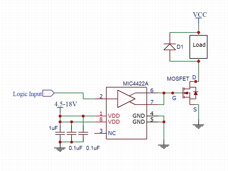
The term ‘low-side’ means that the MIC4422 is generally used to drive N-Channel MOSFETs that are connected between the load and ground to control power to the device as shown in example schematic.
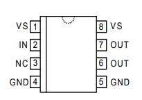
The package has two pins for all functions except for the logic input due to the high power handling capability of the device. Each of the duplicate pins must be connected.
To handle the fairly high transient currents during switching, the VDD pins should be bypassed with a 1uF low ESR ceramic cap and two 0.1uF ceramic caps all placed in parallel across the VDD and GND pins as closely as possible. Note that the VDD pins are the voltage that you want to drive the gate with to achieve saturation. This will typically be greater than the 3.3 or 5V that the control logic is running at.
The example schematic below shows the typical use for these parts to drive an N-Channel Power MOSFET to control a load.
The MIC4422 is packaged in a DIP-8 package for easy prototype use.
If you don’t need that much drive capability and are looking for a dual-channel part, check out the MC34152 below.
Notes:
- For heavy switching applications, it is not recommended to use solderless breadboard construction with this device in order to avoid excess output ringing and overshoot which can damage the device or cause erratic behavior. Projects are best built on PCB breadboards.
TECHNICAL SPECIFICATIONS
| Input | Logic High | > 2.4V |
| Logic Low | < 0.8V | |
| Supply Voltage | Maximum | 18V |
| Minimum | 4.5V | |
| Output Current | Peak | 9A |
| Continuous | 2A | |
| Rise/Fall Time | 25nS | |
| Package | DIP-8 | |
| Package Type | Plastic, thru-hole | |
| Mfr | Micrel | |
| Datasheet | MIC4422 |


