

- ★Product Description
- ★About us
- ★Custom cable
Model MP3-TF-16P / FN-M16P
DESCRIPTION
Small, low-cost player that plays MP3 and WAV files from an SD card and can directly drive a 3W speaker or provide an analog stereo output. Very handy for adding sound to a project.
PACKAGE INCLUDES:
- Mini MP3 and WAV File Player (model MP3-TF-16P / FN-M16P)
KEY FEATURES OF MINI MP3 AND WAV FILE PLAYER:
- Supports MP3 and WAV file decoding
- Supports FAT16 and FAT32 file system
- Supports sampling rates (kHz): 8 / 11.025 / 12 / 16 / 22.05 / 24 / 32 / 44.1 / 48
- 24-bit DAC output supports 90dB and SNR 85dB
- Supports stand-alone pushbutton (AD Key) control mode
- Supports serial control by microcontroller
- Supports USB connection for direct file upload/download to SD card
- Supports up to 32GB micro-SD card
- Supports thousands of files for playback
- supports random playback
- Built-in 3-watt amplifier can directly drive a small speaker
- 30 levels adjustable volume and 6 levels adjustable EQ
- Busy output available for monitoring play state
- 3.3V logic compatible
- 5V module operation
The module easily connects to a microcontroller like Arduino, ESP32 or Teensy for control through a serial port and can also be used standalone with pushbutton inputs only. It even supports a USB port connection for file transfer to and from the SD card.
These modules use the same YX5200 audio and YX8002 amplifier chips as used in the original DFPlayer Mini.
The DFRobotDFPlayerMini.h library supports these modules and is what we use in our examples on this page. The module can also be directly controlled without using a library.
To facilitate using these modules, we have introduced a Mini MP3 and WAV File Player Baseboard. It is available as a baseboard only, or fully stuffed with a Mini Player Module, 32GB MicroSD with example files and SD card adapter. Click on the pic for more info.
CONNECTIONS
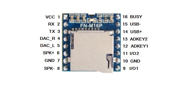
The module has 16 pins with standard 0.1″ pin spacing on 0.7″ centers and work nicely in a solderless breadboard.
Keep in mind that the module serial I/O is 3.3V compatible. If using with a 5V MCU, a 1K series resistor on the RX input line of the module is recommended to provide current limit protection for the module. Alternatively a logic level shifter can be used. A resistor is not needed on the TX line since it is an output. No resistors are needed if connecting to a 3.3V MCU.
Module Pinout

| Pin # | Name | Description | Notes |
| 1 | VCC | 3.2 – 5VDC | 4.5 – 5V recommended |
| 2 | RX | Serial Input | 3.3V TTL level |
| 3 | TX | Serial Output | 3.3V TTL level |
| 4 | DAC_R | Analog Audio Out Right Ch | Drive headphone or external amp |
| 5 | DAC_L | Analog Audio Out Left Ch | Drive headphone or external amp |
| 6 | SPK2 | Speaker – Connection | Drive speaker up to 3W |
| 7 | GND | Ground | |
| 8 | SPK1 | Speaker + Connection | Drive speaker up to 3W |
| 9 | IO1 | Trigger Port 1 | Short press = play previous Long press = decrease volume |
| 10 | GND | Ground | |
| 11 | IO2 | Trigger Port 2 | Short press = play next Long press = increase volume |
| 12 | ADKEY1 | A/D Port 1 | Multi-key analog input |
| 13 | ADKEY2 | A/D Port 2 | Multi-key analog input |
| 14 | USB + | USB+ DP | USB + data connection |
| 15 | USB – | USB- DM | USB – data connection |
| 16 | Busy | Busy output | Low = working (playing) High = standby |
RECOMMENDED SD CARDS
For use in this player, virtually any micro-SD card will work. The maximum size limitation is 32GB.
SOUND OUTPUT
The module can directly drive a small speaker and also has an analog stereo output that can be used to drive an amplifier, powered speaker or headphones.
The volume can be controlled through the serial port from 1 to 30. To set volume to mid-level, the command would be player.volume(15);
There is also an EQ setting that goes from 1-6. The software library defines them as:
player.EQ(DFPLAYER_EQ_NORMAL); // Default
//player.EQ(DFPLAYER_EQ_POP);
//player.EQ(DFPLAYER_EQ_ROCK);
//player.EQ(DFPLAYER_EQ_JAZZ);
//player.EQ(DFPLAYER_EQ_CLASSIC);
//player.EQ(DFPLAYER_EQ_BASS);
A blue LED on the module comes on when an SD card is inserted and blinks when a file is being played.
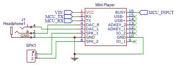
The schematic shows the typical connections used for controlling the module through a serial port and hooking up a speaker connection and the analog output to a phono jack. The BUSY pin connects to an input on the MCU so it can easily tell if it is currently playing a file by occasionally monitoring the pin. The module can also be queried over the serial port to see if play has finished instead of using the BUSY pin.

Speaker Output
The module has a built-in 3W YX8002 amplifier IC that can drive a speaker at up to 3W. Either a 3, 4 or 8ohm speaker can be used and is attached across the SPK1 (+ lead) and SPK2 (- lead) pins which are driven differentially.
Though the output is a single speaker, both right and left audio channels are mixed on the input of the amplifier.
Sound output is pretty decent and a 3 or 4 ohm speaker will provide more sound volume than an 8 ohm speaker.
When driving a speaker at higher volumes, the module can draw a fair amount of fluctuating power from the power supply, so keep power management in mind when using the direct speaker connection. If using loudest volumes, it will usually be best to use a separate power supply for the module rather than running off the 5V output of an Arduino for instance. At fully volume, the built-in amplifier IC can get quite hot.
See the Our Evaluation Results section for more information about the challenges with using the direct speaker output.
Analog Output
The DAC_L and DAC_R outputs of the module are the left and right analog audio channel outputs of the YX5200 chip. They also as serve as inputs to the YX8002 amplifier IC for driving an attached speaker if one is connected
The analog outputs can be used to connect to an amplifier input, powered speakers or headphones.
FILE MANAGEMENT
The module supports both MP3 and WAV files that are stored on the micro-SD card and placed in the card reader of the module.
The module provides several methods of organizing files on the micro-SD card. These chips and modules where originally created for embedding into products with or without MCU control so the file structure has specific requirements. Some of those methods create confusion, so we will focus first on putting the files into folders which is the most flexible method and works best in most situations. The example program at the bottom of the page uses this file management method.
Placing Files into Folders
In this use case, one or more folders (up to 99) are created to hold the files. The folders must be named sequentially 01, 02, 03….99. Each folder can hold up to 255 files. Note that the folder name must be 2-digit, so the leading zero is required.
The files placed into those folders must also be sequentially named. The first file would be named 001.MP3 (or 001.WAV) up to 255.MP3 (255.WAV). Note that the file name must be 3-digit, so the leading zeros are required to pad.
With 99 folders each holding up to 255 files, in theory you can store up to 25,245 files. Maximum number of files will also depend on file sizes, but a 32GB SD card holds a lot of data.
The nice thing about using this method is that the file number can be prefixed onto an existing file name. So instead of 001.MP3, it could be 001Zombie Screams.MP3 which makes it much easier to keep track of the different files.
The format of the command to play the file using this method is player.playFolder(folder, file); ‘player’ is whatever name that has been assigned to the DFRobotDFPlayerMini object that is created. The leading zeros can be ignored when issuing the play commands.
To play the 001Zombie Screams.MP3 in folder 02 for example, the command would be player.playFolder(2,1);
Placing the Files into Special MP3 Folder
Another file organization that can be used is to create a special folder named ‘MP3’ and dump all the files into the one folder.
In this case the file names are limited to 0001, 0002, 0003….3000.
The upside is that you can put up to 3000 into one folder, but the naming is limited to using the numeric values only.
To play the file named 0001, the command would be player.playMp3Folder(1);
Placing the Files into the Root Directory
You can also just dump all the files into the root directory and not worry about folders.
In this case the module automatically assigns file 0001 as the first file that is copied to the SD card, 0002 as the second file copied and so on. It doesn’t go by the file name at all.
To play the first file copied, the command would be player.play(1);
This method would work fine for a production product where you are just cloning the SD card files which have already been organized, but it adds a lot of unnecessary confusion when working with the module and adding and deleting files.
CONTROLLING THE MODULE
Serial Control
Serial control is how this module is typically controlled. It communicates over 3.3V TTL level serial on the TX and TX pins. The serial link is cross-connected between the MCU and module, so RX ->TX and TX -> RX. Communication speed is fixed at 9600 baud.
The serial communications include checksum and feedback bits (request return information) which the library takes care of. Refer to the datasheet if you are interested in the details or want to program the module directly without using the library.
USB File Mode
The module has two pins USB+ and USB- for making a USB 2.0 connection to a host computer for uploading or downloading files directly to the SD card rather than removing and inserting the SD card into the computer.
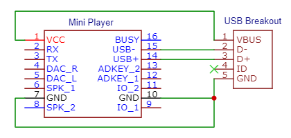
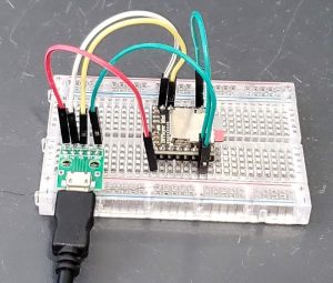
A USB connector breakout adapter can be used to connect the module to a USB port on a computer using a standard USB cable as shown here. A USB cable can also be split apart to make the wiring connections directly. If powering the module from USB as we are doing here, the 5V and Ground from the USB should also be connected to the module.
This setup is only working with the USB connection, but obviously the serial lines could also be connected to an MCU and speakers connected so we can modify files through the USB while also working on the control programming using an MCU.
If the module has external power rather than being powered through the USB, the USB power should not be connected but the USB ground must be connected.
When an SD card is inserted and the USB cable is connected to a computer, the SD card will show up in the file manager as a USB drive. Files can easily be added or deleted just like a USB thumb drive.
This functionality can be handy if you don’t have an SD card slot on your computer or you want to do a lot of file manipulation while working with the module.
The speed of the connection is relatively slow at around 350KB/s, so if working with large files it can take awhile for file transfers.
When USB is connected, the blue LED flashes quickly and if a file is playing, playback is suspended while the USB is active.
AD Key Mode
The module is capable of being directly controlled with just pushbutton inputs and can support up to 20 pushbuttons using the AD Key Mode.
AD Key refers to using a an Analog to Digital converter to read the value of several pushbutton switches (keys) that are connected to it. The switches are connected in parallel with specific resistor values in series with each of the switches that allow the module to know which button has been pressed by the value it reads. The resistors form a voltage divider network with a resistor already on the YX5200 chip and the read voltage level determines the key being pressed.
The module has 2 A/D converter inputs ADKEY1 and ADKEY2 and each supports up to 10 pushbuttons. The key functionality is baked into the module.
I/O Key Mode
The module also has two digital I/O input pins IO1 and IO2. These inputs support two pushbuttons connected to ground to control the main functions of play next / previous file and volume up / down by using either short or long button presses. The functionality is baked into the module.
Using direct pushbutton inputs is mainly useful for creating a small limited function music player without requiring an MCU to control it, but where’s the fun in that?
Refer to the data sheet for more info on using the ADKEY or I/O modes including schematics.
OUR EVALUATION RESULTS:
Adding music or sound effects to a project is a common desire, especially when working with something like a Halloween prop and these make it cheap and easy to do and can be controlled by virtually any MCU.
One of the nice things about these modules is that they can be commanded to play a file through a simple serial command and then the MCU is free to go off and do other things. It can check the BUSY line to see the current play status of the module or can query the module through serial. Having a built-in amplifier and being able to directly drive a speaker can also be quite handy for many applications though the direct speaker output can create tricky issues with some setups.
All specifications quote a 3.2 – 5V input power. In our testing, anything below about 4.5V resulted in incorrect operation.
The modules have marginal system grounding, probably as a result of trying to keep the price low and the modules small. Because of this, the analog outputs usually work with little drama, but when trying to drive a speaker directly that requires significant fluctuating power, it can over tax the power supply, introduce system noise, create ground bounce and various other issues. The usual result is unpleasant noise coming out of the speaker instead of the sound you were hoping to hear. This can especially be a problem when using with solderless breadboard mounting and longer wires.
Mini MP3 and WAV File Player Example Program
/*
  Mini MP3 and WAV File Player Example Program

  This program simply initializes the player and plays a file
  from the SD card then repeats.

  Create a directy 01 on the SD card
  Add an MP3 or WAV sound file to the 01 directory that has been renamed
  to 001 or you can add 001 to the front of the file name

  We are using SoftwareSerial so that we can use any 2 convenient pins.
  Just be sure that the pin used for RX on the MCU has interrupt capability.
  We are using pins 2 & 3 which support interrupts on Uno
  TX is digital pin 2 (connect to RX pin 2 of Mini Player)
  RX is digital pin 3 (connect to TX pin 3 of Mini Player)
  Add 1K resistor to RX input of Mini Player if used with 5V MCU

  We have the BUSY output pin 16 connected to MCU pin 5 to monitor play state

  Uses the DFRobotDFPlayerMini and SoftwareSerial libraries
*/
#include "DFRobotDFPlayerMini.h"
#include "SoftwareSerial.h"

#define PLAYER_BUSY_PIN 5         // Busy input pin

// Create the serial port object
SoftwareSerial playerSerial(3, 2);  //RX, TX
// Create the Player object
DFRobotDFPlayerMini player;
//===============================================================================
//  Initialization
//===============================================================================
void setup() {

  // Init USB serial port for debugging
  Serial.begin(9600);
  // Init serial port for DFPlayer Mini
  playerSerial.begin(9600);
  // Setup input pin to monitor busy output pin of module
  // Enable pullup since pin is active LOW
  pinMode(PLAYER_BUSY_PIN, INPUT_PULLUP);

  // Start communication with the Mini Player
  if (player.begin(playerSerial)) {  // Returns TRUE if successful
   Serial.println("Player OK");
    // Set volume to maximum (0 to 30).
    player.volume(30);
    // Play file starting with 001 in folder 01
    player.playFolder(1,1);
    delay(2000);  // Wait for the player to start playing
  } else {                                // Returns FALSE if unsuccessful
    Serial.println("Connecting to Mini Player failed!");
    while(-1); // go no further if no connection
  }
}
//===============================================================================
//  Main
//===============================================================================
void loop() {
  // if the busy pin goes HIGH, the file has ended, so replay the file
  if(digitalRead(PLAYER_BUSY_PIN) == HIGH){
      player.playFolder(1,1); // Loop
      Serial.println("Loop playing file");
      delay(2000);  // Give player time to start playing before checking BUSY pin
  }
}
BEFORE THEY ARE SHIPPED, THESE MODULES ARE:
- Sample inspected and tested per incoming shipment.
FURTHER READING:
DFRobot DFPlayer Mini Wiki with useful information on using these types of modules with their software library
Notes:
- none
TECHNICAL SPECIFICATIONS
| Operating Voltage | 4.5 – 5VDC (recommended) | |
| MP3 Audio Formats | 8/11.025/12/16/22.05/24/32/44.1/48 (kHz) | |
| MP3 Audio Decoding | 11172-3 and ISO13813-3 Layer3 audio decoding | |
| USB Port | USB 2.0 | |
| UART Port | 3.3V TTL Level Serial Port | |
| Module Dimensions | 20.5 x 20.5mm (0.8 x 0.8″) | |
| Country of Origin | China | |
| Mfr | Flyron Technology | |
| Datasheet |
Embedded MP3 Audio Module |


