


Red LED Indicator Module
Red LED Indicator Module
Compatible JST cables for sensors and modules — secure & reliable. Shop now.

Couldn't load pickup availability


- ★Product Description
- ★About us
- ★Custom cable
8 Common Cathode LEDs with series resistors.
DESCRIPTION
This module makes it easy to work with LEDs in a project.
PACKAGE INCLUDES:
- Red LED Indicator Module with pins soldered
KEY FEATURES OF RED LED INDICTOR MODULE:
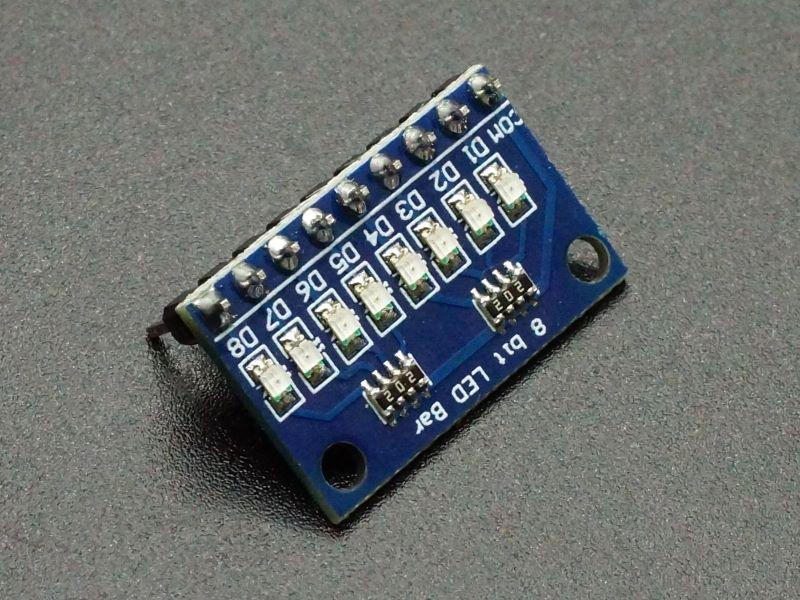
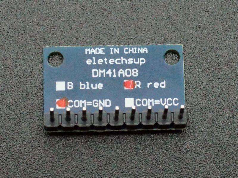
- 8 red LEDs in CC (Common Cathode) configuration
- Built-in 2K current limiting resistors
- 3.3 and 5V compatible
The first thing everyone does when starting to work with microcontrollers is to hook up an LED with a current limiting resistor and make it blink. Great fun! at least the first time. Fast forward awhile and when you have a need to wire up some LEDs for a project, dragging out the LEDs, finding enough that match, finding the correct value resistors and hooking it all up starts to seem more like work than fun… or perhaps thats just me.
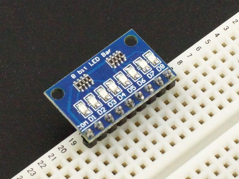
These modules make adding 1 to 8 LEDs to a project very easy and tidy. More than 8 LEDs can be added by simply adding more modules.
The modules have 2K current limiting resistors which keep current requirements low when using with standard 3.3V or 5V logic so any microcontroller can drive them and also helps keep the LED brightness at a comfortable level. It also allows the LEDs to be used in higher voltage applications of up to 24V.
A logic HIGH on the D1-D9 pins turns the corrosponding LED on. A logic LOW turns it off.
Module Connections
There is a 9-pin header on the assembly for connections. The COM pin is the common pin and connects to the Cathode of all the LEDs. D1-D8 connect to the anodes of each LED.
1 x 9 Header
- COM = Ground
- D1 – D8 = Connectst to digital I/O pins on microcontroller.
OUR EVALUATION RESULTS:
 These modules really are quite handy to quickly add some indicator LEDs to a project.
If you are working with an Arduino like an UNO or Mega2560 and don’t need more than 6 LEDs, you can clip the D7, D8 pins off the module and insert the module directly into the female header on the Arduino with the COM pin going into the GND connection and the LED pins going into D8-D13 with no wiring or breadboard necessary to mount the module on.
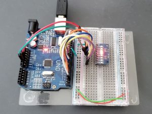
The program below simply scans the LEDs up and down. The module COM pin is connected to ground and the LED pins D1-D8 are connected to pins D2-D9 on the microcontroller. These can be changed to any convenient pins if desired.
LED Scanner Program
/*
Scan 8 LEDs back and forth

Simply scans the LEDs in sequence in one direction and then in the
reverse direction and repeats forever.  Change DELAY_TIME to change speed

Connect COM pin to ground
Connect D1-D8 pins on module to D2-D9 on microcontroller

Change DELAY_TIME to change the speed
*/
const int DELAY_TIME = 75;    // Change to change speed
//===============================================================================
//  Initialization
//===============================================================================
void setup() {
  // initialize digital pins 2-9 as outputs.  Can change to any 8 digital pins
  pinMode(2, OUTPUT);
  pinMode(3, OUTPUT);
  pinMode(4, OUTPUT);
  pinMode(5, OUTPUT);
  pinMode(6, OUTPUT);
  pinMode(7, OUTPUT);
  pinMode(8, OUTPUT);
  pinMode(9, OUTPUT);
}
//===============================================================================
//  Main
//===============================================================================
void loop() {
  for(int i = 2; i <= 9; i++){  // Ramp the LEDs up
  digitalWrite(i, HIGH);        // Turn the LED ON
  delay(DELAY_TIME);            // Wait for a bit
  digitalWrite(i, LOW);        // Turn the LED OFF
  }
  for(int i = 9; i >= 2; i--){  // Ramp the LEDs down
  digitalWrite(i, HIGH);        // Turn the LED ON
  delay(DELAY_TIME);            // Wait for a bit
  digitalWrite(i, LOW);         // Turn the LED OFF
  }
}
BEFORE THEY ARE SHIPPED, THESE MODULES ARE:
- Sample inspected and tested per incoming shipment.
Notes:
- None
TECHNICAL SPECIFICATIONS
| Maximum Ratings | ||
| Vcc | 24V (3.3 – 5V typical) | |
| IMax | Maximum Current Draw per LED | < 10mA |
| Operating Ratings | ||
| LED Configuration | Common Cathode | |
| LED Current | 3.3V | 0.75mA (typ) |
| 5V | 1.55mA (typ) | |
| Dimensions | L x W (PCB) | 23 x 15mm (0.90 x 0.60″) |


