

- ★Product Description
- ★About us
- ★Custom cable
DESCRIPTION
The Romeo V2.2 is a robotics oriented all-in-one board based on the Arduino Leonardo ATmega32U4 chip with motor control and other added functionality on-board.
PACKAGE INCLUDES:
- Romeo V2.2 Board (Arduino compatible)
KEY FEATURES OF ROMEO V2.2:
- ATmega32U4 processor running at 16MH w/built-in serial to USB converter
- 32KB Flash memory
- 20 Digital I/O
- 7 PWM shared with the digital I/O
- 12 Analog inputs that can also be used as digital I/O for a total of up to 26 digital I/O
- 2-Channel L298 2A DC motor driver
- 1-Channel L298 2A stepper motor driver
- Separate servo motor 5V supply input
- Integrated Xbee wireless form factor socket
- Integrated APC220 RF and DF-Bluetooth module sockets
- Duplicated I/O pins with male and female headers plus dedicated power & ground pins
- Compatible with many R3 shields
- 3 sets of I2C connections
- 1 Hardware serial port
- 6-20V input power or powered via USB connection
This board is a clone of the DFRobot Romeo V2.2 board. The board provides an all-in-one solution for driving motors and handling sensors. It is based on the Arduino Leonardo ATmega32U4 chip and should be programmed using the Arduino Leonardo board selection in the IDE.
This platform packs a lot into a small space. It can be a handy platform, but also a bit overwhelming if you are new to Arduino. Be sure to pay particular attention when hooking up power. To make things easier, we download and test using the software below and leave it in the board when you get it.
Board Power
USB:
As with any Arduino, power can be supplied via the USB connector. This board uses the small micro USB connector so ensure you have one on-hand. Use some care when plugging and unplugging the cable to not pull up on the connector to avoid possible damage.
When using USB power, the board logic circuits are powered up and it can be programmed and debugging can occur, but the motors cannot be driven.
To use the board with motors, an external power supply must be connected to the VIN terminal input.
VIN:
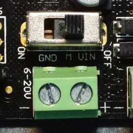
The main board and DC motor power typically comes in on a screw terminal labeled 6-20V VIN.
Power on this connector can range from 6V to 20V and can be provided using batteries or an external power supply.
Note: There is no reverse polarity protection on this connection. Ensure you have the polarity correct before applying power.
The board has a main power ON/OFF slide switch next to the VIN terminals. When switched OFF, this disconnects the VIN input from the rest of the board. This is handy for killing power to save on battery power or in the event of a robot that is trying to take over the world. That was Skynets big mistake – forgetting to include an ON/OFF switch
You will see warnings on some websites that if you are using a VIN voltage greater than 12V that you must ensure you turn this switch off before connecting a USB cable to avoid damaging the Romeo board. There is nothing in the circuit that would indicate this is an actual issue and we have tested the board to 20V input with a USB cable connected without noting any problem.
The VIN power is applied directly to the L298 motor controller for driving DC and stepper motors so the VIN voltage is normally tailored to whatever is required to drive the DC motors. This is typically in the 6 – 9V range if using batteries.
5V & 3.3V Logic Power:
The VIN input is also fed into a DC-DC converter circuit that drops it to 5V to supply power to the logic circuits on the board.
The DC-DC converter provides the important function of creating electrical isolation between the electrically noisy motors and the noise sensitive logic circuits.
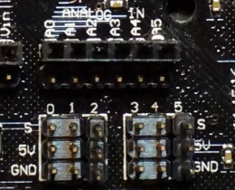
The 5V from the DC-DC converter is also made available on the 3-pin headers next to the analog inputs along with ground connections. This provides clean power for connecting sensors to the A0 – A5 inputs. These connections are labeled ‘5V‘.
The 5V power is also fed to a 3.3V linear regulator to provide 3.3V to the XBee connector and 3.3V general purpose output header.
Servo Power:
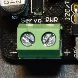
There is a separate screw terminal labeled ‘Servo PWR‘ for connecting power to any servos that are being used with the board.
Though servos typically operate on 5V, they cannot be operated off the same supply as the 5V logic due to the electrical noise that they create which can create erratic behavior of the logic circuits.
If using servos, a separate 5V power source needs to be connected to this connector. Some servos can operate on 6V, so if the main input power to VIN is 6V, you may be able to use the same 6V power source for the servo power as well.
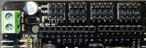
This servo power is labeled ‘PWR‘ and is made available on the 3-pin headers on the digital I/O along with ground.
If you are not using servos and you want to use these PWR pins to supply power to sensors connected to the digital I/O lines, you can connect the Servo PWR connector or one of the PWR pins to the on-board 5V logic supply.
DC Motor Control
Motor Control Jumpers:
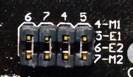
There are 4 jumpers on the board labeled M1-2, E1-2. M stands for Motor and E is for Enable.
When these jumpers are installed, the digital I/O pins D4-D7 are connected to the L298 motor driver IC to provide motor control functionality.
If motors are not being used, these jumpers can be removed and the D4-D7 pins then become available for use as general purpose digital I/O.
Motor Connections:
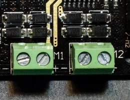
There are two motor screw terminal blocks for connecting motors. These are labeled M1 and M2.
You can connect more than one motor to each of the outputs as long as the total motor current draw does not exceed 2A. This is commonly done when working with a 4-wheel drive robotic platform where the two motors on one side are connected to M1 and the two motors on the other side are connected to M2.
Note that the wiring to M2 is reversed from M1. If you want the motors to turn in the same direction, connect the red wire to the ‘-‘ terminal and the black wire to the ‘+’ terminal on the M2 connector.
Software Control:
The board uses pins D4 – D7 for motor control. Pins 5 & 6 are PWM capable pins and connect to the L298 chips two Enable inputs to provide speed control by modulating the enable input ON/OFF.
Pins 4 & 7 are connected to the L298 chip IN inputs to provide direction control. Usually there are 2 pins used to determine the direction of rotation for each motor, but this board has an inverter that provides an inverted version of the signal to the two IN pins for each motor. This reduces the number of pins used, but it does remove the ability to do dynamic braking which usually isn’t an issue for most projects. Reducing the speed control pins to a PWM value of zero will get things stopped.
| Speed Pins | Speed Control | Direction Pins | Direction Control | ||
| Motor 1 | D5 | PWM 0-255 | D4 | HIGH = Forward | LOW = Reverse |
| Motor 2 | D6 | PWM 0-255 | D7 | HIGH = Forward | LOW = Reverse |
Pushbuttons:
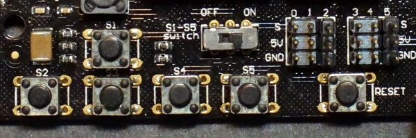
There are 6 pushbuttons on the board. 5 are general purpose pushbuttons and 1 is the RESET button.
The general purpose pushbuttons S1 – S5 all connect to a resistor voltage divider which connects to analog input A0. Reading the analog voltage value on A0 allows you to tell which button is being pushed.
The ‘S1-S5 Switch‘ when switched to ON, connects the 5 pushbuttons to A0. If you are not using the pushbuttons, you can turn the switch OFF and use A0 for another purpose.
If you are attempting to read the switches using A0 and getting random or spurious results, make sure that this switch is ON. When OFF, the A0 input will be left floating thus giving random readings on the analog port.
OUR EVALUATION RESULTS:
These are clone assemblies with gold plating and fair build quality.
The boards have the Leonardo bootloader added and the program below is loaded to test the basic functionality of the board and is left in the board to make it easy to get up and started using the assembly.
To get started: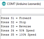
- Connect a micro USB cable between the board and computer
- Open the Arduino IDE and select ‘Leonardo’ as the board type
- Select the COM port that the board appears on
- Open the Serial Monitor window and ensure 9600 baud is selected.
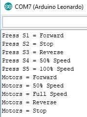
With that accomplished, the board should display the list of menu commands shown to the right.
Pressing the S1-S5 buttons should flash an LED on the board and report the action that button is causing in the Serial Monitor window.
If the buttons do not seem to be working correctly or working on their own, double-check that the S1-S5 Switch is set to the ON position.
To take the next step and do some basic motor control:
- Hook up a suitable power supply of 6-20V to the VIN connector. Double-check polarity with the positive lead going to the ‘+’ terminal.
- Hook up one or two smaller motors to the M1 and/or M2 terminals
- Turn the VIN switch to the ON position
- Pressing the buttons should now start controlling the motors.
Things to Watch for:
Download issues – Because of the Leonardo architecture where the main processor is also the USB port, the PC may reassign (re-enumerate) the COM port if the board is reset or cables are reconnected. If you experience issues with downloading, ensure that the current COM port is selected in the IDE. The COM port will generally identify the device as ‘Leonardo’.
DC Motors are not working – Ensure the motor switch is ON with a valid motor voltage input on VIN connector.
Motor turning wrong direction – Motor wiring reversed between M1 and M2. You can swap leads as needed to get the rotation orientation you need.
Erratic button presses being detected – Ensure that the button switch is ON. When OFF, the A0 input is left floating and can be detected as random button presses.
Program was working but won’t run if I remove USB cable – If you are not using the USB link, be sure to not have the wait for serial command in your program or it won’t work once the USB cable is removed. You can comment it out as shown here.
Serial.begin(9600);
// while (!Serial) {}
These boards don’t have the color coding on the headers for power/ground/signal, just be sure to follow the board markings.
Romeo Test Program
/*
   Romeo Board Test

   Reads keys and drives both motor outputs based on the key pressed
   S1 = Forward
   S2 = Stop
   S3 = Reverse
   S4 = 50% Speed
   S5 = 100% Speed
*/
const int BTN_NONE = 0;
const int BTN_FORWARD = 1;
const int BTN_STOP = 2;
const int BTN_REVERSE = 3;
const int BTN_HALF_SPEED = 4;
const int BTN_FULL_SPEED = 5;

//  Motor A
int const M1_DIR = 4;
int const M1_EN = 5;
//  Motor B
int const M2_EN = 6;
int const M2_DIR = 7;

int key_Pressed = BTN_NONE;

void setup() {
  pinMode(13, OUTPUT);  //we'll use the debug LED to output a heartbeat
  Serial.begin(9600);
  while (!Serial);    // Pause until serial link is established.
                      // Comment out if not using USB connection

  // Print instructions one time
 Serial.println("Press S1 = Forward");
 Serial.println("Press S2 = Stop");
 Serial.println("Press S3 = Reverse");
 Serial.println("Press S4 = 50% Speed");
 Serial.println("Press S5 = 100% Speed");
}

void loop()
{
  key_Pressed = Read_Buttons();  // read the buttons

  switch (key_Pressed)           // Do something based on the button pressed
  {
    case BTN_FORWARD:
      {
        digitalWrite(M1_DIR, HIGH);
        digitalWrite(M2_DIR, HIGH);
        Serial.println("Motors = Forward"); // Print the key that was pressed
        break;
      }
    case BTN_STOP:
      {
        digitalWrite(M1_EN,LOW);
        digitalWrite(M2_EN,LOW);
        Serial.println("Motors = Stop");
        break;
      }
    case BTN_REVERSE:
      {
        digitalWrite(M1_DIR, LOW);
        digitalWrite(M2_DIR, LOW);
        Serial.println("Motors = Reverse");
        break;
      }
    case BTN_HALF_SPEED:
      {
        analogWrite(M1_EN, 128);
        analogWrite(M2_EN, 128);
        Serial.println("Motors = 50% Speed");
        break;
      }
    case BTN_FULL_SPEED:
      {
        digitalWrite(M1_EN, HIGH);
        digitalWrite(M2_EN, HIGH);
        Serial.println("Motors = Full Speed");
      }
    case BTN_NONE:
      {
        break;
      }
  }
  if(key_Pressed != BTN_NONE)   // Blink LED and debounce switch
  {
  digitalWrite(13, HIGH);  // Turn LED on
  delay(500);              // Delay for switch debounce & LED blink
  digitalWrite(13, LOW);   // Turn LED off
  }
}
//===============================================================================
//  Read Buttons - Subroutine to read the ADC and return the button value
//===============================================================================
int Read_Buttons()
{
  int adc_key_in = analogRead(A0);      // read the value of the key resistor divider
  // The buttons are connected to a voltage divider that feeds into analog input A0.
  // By looking at the voltage level, we can tell which button has been pressed if any.
  // With no button pressed, the voltage will be pulled up to Vcc.
    //Serial.println (adc_key_in);
  if (adc_key_in >= 1000) return BTN_NONE; // Most likely result, so it is the first option.
  if (adc_key_in < 30)   return BTN_FORWARD; // Work our way up the voltage ladder and return 1st valid result
  if (adc_key_in < 200)  return BTN_STOP;
  if (adc_key_in < 500)  return BTN_REVERSE;
  if (adc_key_in < 700)  return BTN_HALF_SPEED;
  if (adc_key_in < 990)  return BTN_FULL_SPEED;

  return BTN_NONE;  // when all others fail, return this...
}
BEFORE THEY ARE SHIPPED, THESE MODULES ARE:
- Inspected
- Leonardo bootloader loaded
- Powered up and the example program is downloaded to verify basic operation including motor control.
- Repackaged in high quality resealable ESD bag for safe storage.
FURTHER READING:
Notes:
- None
TECHNICAL SPECIFICATIONS
| Microcontroller | ATmega32U4 |
| Serial to USB Converter | Built-in Native USB |
| Operating Voltage | 5V |
| Input Voltage (recommended) | 7-12V |
| Digital I/O Pins | 20 |
| PWM I/O Pins (Shared with Digital I/O) | 7 |
| Analog Input Pins | 12 |
| DC Current per I/O Pin | 40mA (Max) 20mA (Typ) |
| Hardware Serial Ports | 1 |
| Flash Memory | 32 KBytes |
| SRAM | 2.5 KBytes |
| EEPROM | 1 KBytes |
| Clock Speed | 16MHz |
| Motor Driver IC | L298 |
| Built-in LED | Attached to digital pin 13 |
| USB Connector Style | Micro-B Female |
| Board Dimensions (PCB) | 90 x 85mm (3.5 x 3.3″) |
| Country of Origin | China |


