


SCM TTL to RS-485 Interface Module
SCM TTL to RS-485 Interface Module
Compatible JST cables for sensors and modules — secure & reliable. Shop now.

Couldn't load pickup availability

- ★Product Description
- ★About us
- ★Custom cable
Robust automatic bi-directional interface between TTL and RS-485
DESCRIPTION
The SCM TTL to RS-485 Interface module provides a robust automatic bi-directional interface from TTL to long-line RS-485.
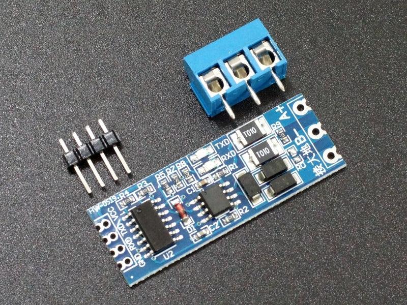
PACKAGE INCLUDES:
- SCM TTL to RS-485 Interface Module
- 4-pin male header
- 3-pin screw terminal block
KEY FEATURES OF SCM TTL TO RS-485 INTERFACE MODULE:
- Automatic bi-directional transmission control
- Uses differential signaling for noise immunity
- Distances up to 1200 meters
- Speeds up to 2.5Mbit/Sec
- Multi-drop supports up to 32 devices on same bus
- Built-in poly fuses for over-current protection
- Built-in transient surge protection diodes for over-voltage protection
- Transmit and receive indicator LEDs
- Comes with connectors and headers for easy hookup
- 3.3V & 5V operation
RS-485 provides for robust serial communications over long distances of up to 1200 meters (4000′) or in electrically noisy environments and is commonly used in industrial environments. It supports up to 2.5MBit/Sec data rates, but as distance goes up, the maximum data rate that can be supported comes down.
You can think of RS-485 as RS232 on steroids. The data starts out as typical TTL level serial as far as the microcontroller is concerned while the RS-485 module takes care of converting the electrical signals between TTL and the differential signaling used by RS-485.
This module is fairly unique in that it automatically takes care of data transmission direction control which makes it easy to use and it also has significant protection circuitry built-in to prevent damage in case of lightning strikes and similar electrical disturbances.
Multi-Drop Support for Multiple Devices
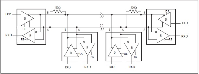
A significant benefit of RS-485 is that it supports multiple devices (up to 32) on the same cable, commonly referred to as ‘multi-drop’.
This works by passing the bus through each device where it picks off the signal as it passes through as shown below.
These devices are typically setup in a Master / Slave configuration with one Master and one or more Slave devices. Since they all share the same bus, to avoid conflict the Slave devices only talk when they are asked for something by the Master such as requesting a temperature reading.
Differential Signaling
The RS-485 uses differential signaling and requires only 2 wires and a common ground.
Differential signals operate by putting the signal on 1 wire and the inverse of the signal on the other wire. This improves the signals noise immunity and the ability to recover the signal at the far end of the cable as noise tends to couple into both lines equally and therefore cancels out at the receiving end.
Wiring RS-485
These two differential data lines are labeled as A & B. On the module, these are available on the screw terminal block end of the board at the solder pads labeled A+ & B-.
When connecting the modules together, the wiring is straight through, so A on one end should be connected to A on the other end and B connects to B.
The wires should ideally be twisted pair. Using twisted pair becomes more important for longer runs or where there is a lot of electrical noise. For simple breadboard testing or other short runs, it is not necessary.
A common ground is needed, but this can often be provided by the earth ground at each end when dealing with shorter runs or bench testing. Network cable is often used for connecting RS-485 as it provides twisted pair, plus it can provide a ground wire as well.
If a shielded cable is used, the shield should be grounded on one end only.
Pull-up and Termination Resistors
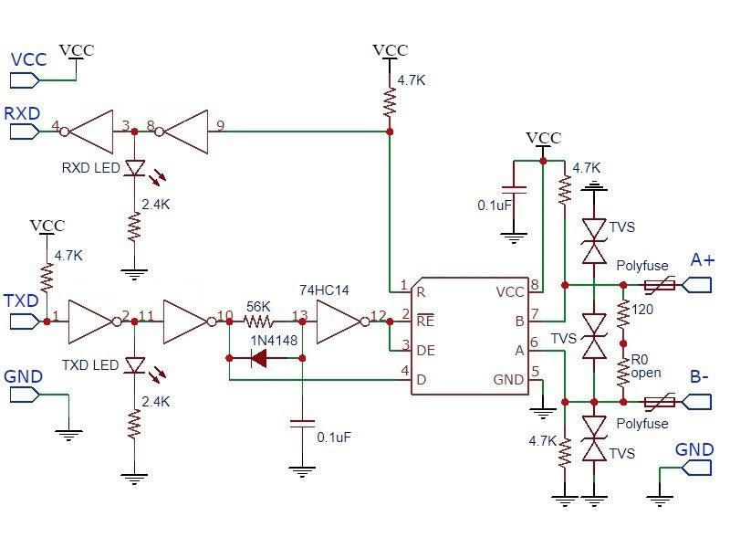
There are 4.7K pull-up resistors on the A/B differential lines. These pull the lines to a known state when data is not being transmitted.
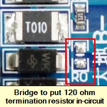
Finally there is a single 120 ohm termination resistor. This resistor goes between the A & B differential lines on the modules at each end of the cable to prevent reflections. As shipped, the resistor is not in-circuit. To put the resistor in-circuit, the solder pads at location R0 should be shorted with solder or a wire. If using in a multi-drop configuration, the modules on the two ends of the line should add these resistors. Modules in the middle of the line should not use these resistors to prevent loading the lines too heavily as shown in the pic above.
For benchtop testing with short cables, this resistor can usually be ignored.
Module Assembly
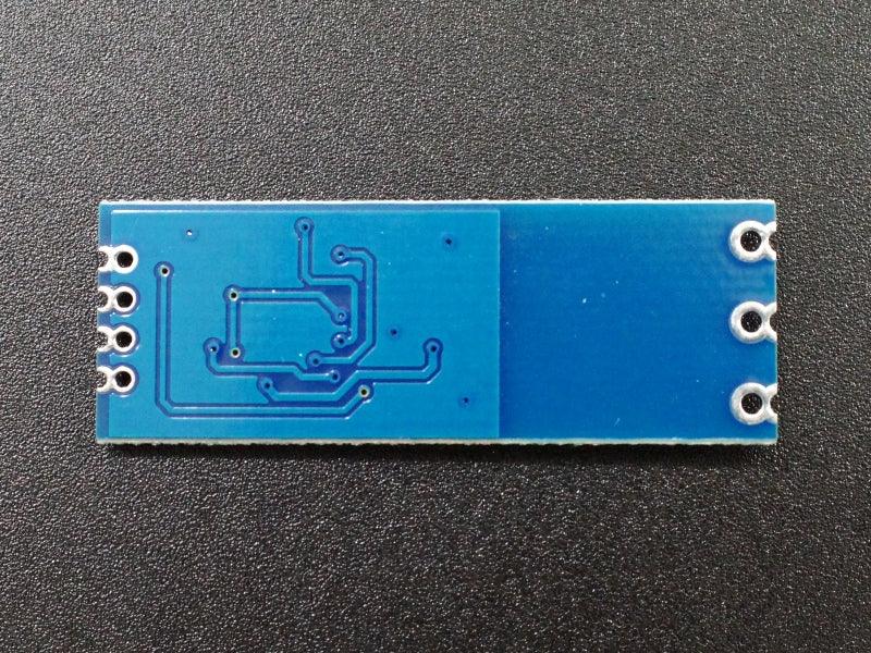
These modules have castellated (half holes) at the edges of the board along with a full hole. This allows the module to be used as a platform board by soldering the edges of it down to solder pads on a board under it.
The modules also come with a strip of male headers and a screw terminal block which can be soldered on either side of the board depending on intended usage. The holes can also be used for direct soldering to wiring.
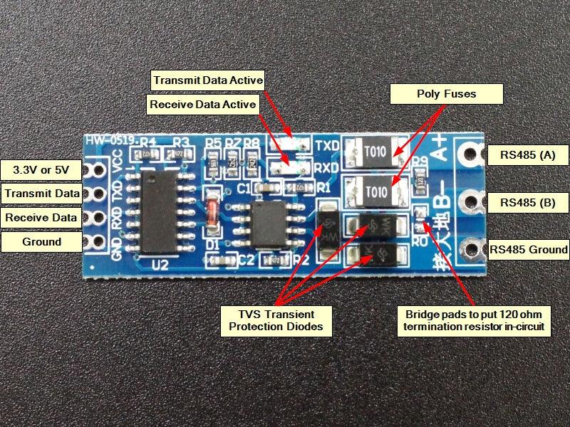
Module Connections
The module has a 4-pin header on the assembly for connections to the MCU. Because this module has auto direction control, it does not require the extra DE/RE pins required by most other RS-485 modules.
1 x 4 Header (TTL Side)
- VCC = Vcc – Connect to 3.3V or 5V to match MCU power
- RXD = Receive Data – Connects to RXD TTL input on MCU
- TXD = Transmit Data – Connects to TXD TTL output on MCU
- GND = Ground. Connects to ground on MCU
1 x 3 Screw Terminal Block (RS-485 Side)
- A+ = Data ‘A’ Non-Inverted Line. Connects to A+ on other modules
- B- = Data ‘B’ Inverted Line. Connects to B- on other modules
- GND = Ground
OUR EVALUATION RESULTS:
The attached schematic is our effort to document this module. The chip markings are removed, so there is a little guesswork as to the exact chips used, but the functionality should be correct.
You will need RS-485 on both ends, so typically you will need two of these modules to implement a basic link unless you are trying to interface with a device that already has RS-485 implemented.
When working with these devices, keep in mind that they are basically just level translators. From the MCUs perspective, the functionality is the same as if two RS-232 serial ports are connected for communicating between the devices. If there is difficulty in using the devices, they can often be temporarily removed from the setup to see if the issue is with the RS-485 or something more basic in the setup. If they are removed from the setup, the RX/TX lines between the microcontrollers need to be crossed i.e. TX1 to RX2 and RX1 to TX2.
Because these devices include automatic direction control, the software is more straightforward than most RS-485 adapter modules.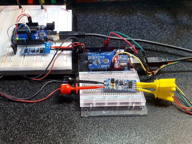
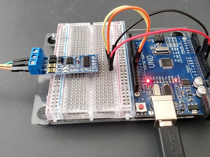
The programs below create both a Master device and a Slave device. For this setup, you will need two Arduinos of any type (or other microcontrollers) and two of the RS-485 modules. You will download the Master software to one device and the Slave software to the second device. The programs use the SoftSerial library for communication in order to leave the hardware serial port available for monitoring the data on the Serial Monitor windows of the two Arduinos. If you are using a version of board that has multiple hardware serial ports, you can use one of those instead if you prefer.
Both devices use the same pins for their soft serial port. Connect as follows from Arduino to RS-485 module on both devices
- Pin 10 (RX) connects to RXD
- Pin 11 (TX) connects to TXD
- 5V connects to VCC (if using a 5V MCU)
- Gnd connects to Gnd
Connect data lines A+ to A+ and B- to B- between RS-485 modules.
The Master device allows you to type any characters in the top portion of the Serial Monitor window and once you press enter, it will send that characters to the Slave device. When the Slave 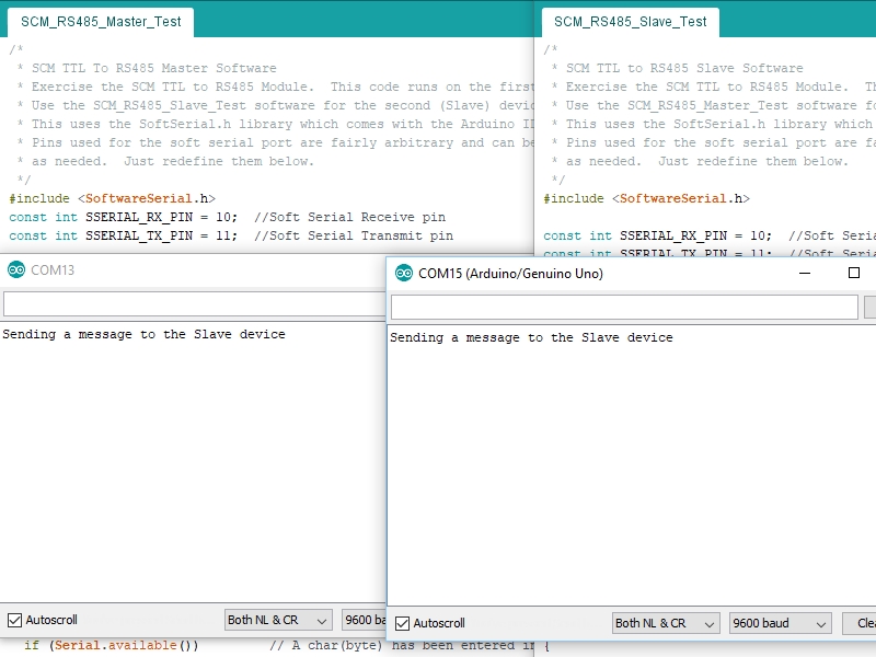 receives the characters, it will send what it received out to its own Serial Monitor window as well as echo it back to the Master device. Once the Master device receives the character back from the Slave, it will also print it out to its own Serial Monitor window. Basically, if you type an ‘a’ and hit ENTER in the top window of the Master device and you see an ‘a’ appear in the bottom window, the command has made a full round trip from the Master to the Slave and back to the Master.
Note that if you want to use the Serial Monitor Window on both the Master and Slave device at the same time, or program both Arduino boards without moving USB cables around and resetting COM ports and Arduino types, you will need to create two instances of the Arduino IDE.
To do that, you just need to open the IDE from the Start menu (or where ever you typically open it) twice. You cannot just open a 2nd window from an existing IDE. Once you have two separate IDEs running, open the Master software in one and the Slave software in the 2nd. Configure both for the COM port and the Arduino type you are using with each window. You will of course also need two USB cables to connect both Arduino boards up to your PC at the same time.
Master RS-485 Device Software
/*
 * SCM TTL To RS485 Master Software
 * Exercise the SCM TTL to RS485 Module.  This code runs on the first (Master)device.
 * Use the SCM_RS485_Slave_Test software for the second (Slave) device
 * This uses the SoftSerial.h library which comes with the Arduino IDE
 * Pins used for the soft serial port are fairly arbitrary and can be changed
 * as needed.  Just redefine them below.
 */
#include <SoftwareSerial.h>
const int SSERIAL_RX_PIN = 10;  //Soft Serial Receive pin
const int SSERIAL_TX_PIN = 11;  //Soft Serial Transmit pin

// Create Soft Serial Port object and define pins to use
SoftwareSerial RS485Serial(SSERIAL_RX_PIN, SSERIAL_TX_PIN); // RX, TX

int byteReceived;
//===============================================================================
//  Initialization
//===============================================================================
void setup()
{
  Serial.begin(9600);           // Start the built-in serial port
  Serial.println("Master Device");
  Serial.println("Type in upper window, press ENTER");

  RS485Serial.begin(9600);   // Start the RS485 soft serial port
}
//===============================================================================
//  Main
//===============================================================================
void loop()
{
  if (Serial.available())         // A char(byte) has been entered in the Serial Monitor
  {
    byteReceived = Serial.read();                   // Read the byte
    RS485Serial.write(byteReceived);                 // Send byte to Remote Arduino
  }

  if (RS485Serial.available())            //Data from the Slave is available
   {
    byteReceived = RS485Serial.read();    // Read received byte
    Serial.write(byteReceived);           // Show on Serial Monitor
   }
}
Slave RS-485 Device Software
/*
 * SCM TTL to RS485 Slave Software
 * Exercise the SCM TTL to RS485 Module.  This code runs on the second (slave)device.
 * Use the SCM_RS485_Master_Test software for the first (Master) device
 * This uses the SoftSerial.h library which comes with the Arduino IDE
 * Pins used for the soft serial port are fairly arbitrary and can be changed
 * as needed.  Just redefine them below.
 */
#include <SoftwareSerial.h>

const int SSERIAL_RX_PIN = 10;  //Soft Serial Receive pin
const int SSERIAL_TX_PIN = 11;  //Soft Serial Transmit pin

// Create Soft Serial Port object and define pins to use
SoftwareSerial RS485Serial(SSERIAL_RX_PIN, SSERIAL_TX_PIN);

int byteReceived;
int byteSent;
//===============================================================================
//  Initialization
//===============================================================================
void setup()
{
  Serial.begin(9600);         // Start the built-in hardware serial port
  Serial.println("Slave Device");

  RS485Serial.begin(9600);   // Start the RS485 soft serial port
}
//===============================================================================
//  Main
//===============================================================================
void loop()
{
  // Watch for data coming in on the soft serial port.  If found, send a copy to the
  // hardware port to display on the local serial terminal and also echo a copy back out
  // the soft serial port to the Master device
  if (RS485Serial.available())        // If data has come in from Master
  {
    byteSent = RS485Serial.read();    // Read the byte
    Serial.write(byteSent);           // Show on local Serial Monitor window
    delay(10);

    RS485Serial.write(byteSent);                     // Send the byte back to Master
  }
}
BEFORE THEY ARE SHIPPED, THESE MODULES ARE:
- Sample inspected and tested per incoming shipment
- Kitted with connectors and packaged in a resealable ESD bag for protection and easy storage.
Notes:
- None
TECHNICAL SPECIFICATIONS
| Operating Ratings | ||
| Vcc | 3.3-5V (typ) | |
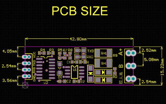
| Dimensions | L x W (PCB) | 43 x 15.5mm (1.7 x 0.6″) |
| Country of Origin | China | |
| Datasheets |
FURTHER READING


