Keszoox
Thermoelectric Peltier TEC1-12706 Cooler Kit
Thermoelectric Peltier TEC1-12706 Cooler Kit
Couldn't load pickup availability
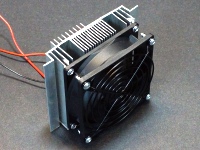
Includes the TEC1-12706 and hot and cold side heatsinks and fans
Description
This is a complete thermoelectric cooling system kit that includes a TEC1-12706 Peltier device. Just need to add a power supply.
PACKAGE INCLUDES:
- TEC1-12706 Peltier Device
- Hot-side heat sink (large)
- Hot-side 90mm cooling fan
- 90mm fan guard
- Cold-side heat sink (small)
- Cold-side 40mm air distribution fan
- Insulating fiber pad
- Thermal paste
- Assembly hardware
KEY FEATURES OF THERMOELECTRIC PELTIER TEC1-12706 COOLER KIT:
- Provides compact cooling form-factor
- Includes TEC1-12706 Peltier device
- Includes hot and cold side fans
- 12V @ 6A operation
Thermoelectric Peltier cooler modules are solid-state heat pumps that use DC current flow to transfer heat from one side of the device (cold side) to the other side of the device (hot side).
These devices are used in small cooling applications such as insulated coolers, small wine cooler cabinets and to cool CPUs in computers. This technology is even used in space craft to move heat from the hot sunlit side of the space craft to the cold side of the space craft.
The Peltier device used in this kit is the TEC1-12706 which is the most commonly used device. The TEC device itself is a fairly small flat plate.
Once assembled into a complete module, the hot side of the device mounts to a large aluminum heat sink with a large cooling fan to pull the heat away from the device. The cold side includes a small aluminum heat sink which acts as a cold radiator. A small 40mm fan is provided that can be attached to this cold side heat sink in order to help distribute the cold if desired for the application. This will also raise the surface temperature of the heat sink and prevent frost formation, though it may cause condensation to form depending on humidity levels.
Because one side is cold and the other is hot, the unit can also be used to warm air. There are easier ways to heat air, but some ice chest applications use this capability to allow the enclosure to be warmed instead of cooled to help keep food warm by reversing the direction of the unit.
Note: It is important to not fully power this device unless the hot side heat sink and fan are in place or damage to the device can quickly result.
Module Power
The TEC module and fans operate from a 12V power supply which needs to be able to supply up to 6A of continuous current. After an initial inrush surge, the complete module generally settles down and draws about 60W of power. One of our 12V 75W Meanwell power supplies is a good fit for powering this module.
Note that the operating voltage can be increased to over 14V so it is possible to run these off a car battery. If you want less cooling for a particular application, the operating voltage can be lowered to something less than 12V.
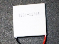
The printed side of the TEC device is the cold side. To check the TEC module before assembling the kit without concerns about damaging the device, you can power it off a lower voltage power supply such as 5V where it will draw about 1.5A and you will feel one side getting colder while the other side gets warmer.
Module Assembly
Follow these steps for completing the assembly of your kit.
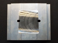
| 1. | Place the large finned heat sink with the fins down so that the flat surface is facing up
|
 |
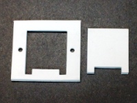
| 2. | Locate the fiber insulating pad. Remove the center punch out and the two small punch outs for the screws
|
 |
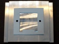
| 3. | Remove the liner from the adhesive side and place the insulating pad onto the heat sink so that the holes in the pad line up with the holes in the heat sink.
|
 |
| 4. | Place the TEC device so that the printed side is facing down and unprinted side is facing upwards.
|
 |
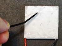
| 5. | Open the small tube of thermal paste and apply approximately half the contents onto the surface of the TEC device without the printing. Spread this paste thinly over the entire surface of the device.
Note: there may be two tubes of thermal paste in which case spread one whole tube on the surface of the device. The thermal paste may either be white or clear. |
 |
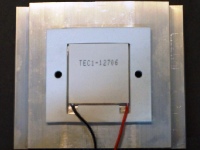
| 6. | Place the side of the TEC device with the thermal paste face-down into the center of the punch-out in the pad so that the leads exit on the side of the pad that has reliefs cut into it.
The printing on the TEC device will be facing up. |
 |
| 7. | Apply the remaining thermal paste onto the exposed side of the TEC device and similarly spread it out thinly across the entire surface of the device. | 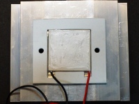 |
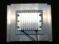
| 8. | Next place the small heat sink flat side down onto the TEC device, aligning the screw holes in the heat sink with the holes in the insulating pad.
Note: Some small heat sinks have threaded holes. Others will have unthreaded holes and 2 nuts will be provided to tighten these screws. |
|
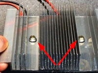
| 9. | Use the two screws with black plastic shoulder washers to screw the two heat sinks together and thus capture the TEC device between them. The screws are inserted from the large heat sink side and screw into the threaded holes in the small heat sink.
Note: Some kits ship with small heatsinks that are not threaded. Those kits include nuts to use for fastening the heat sinks together. In addition, some kits have separate nylon shoulder washers that can be used under the head of the screws and the nuts. |
 |
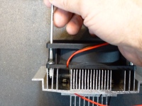
| 10. | Mount the large 90mm fan to the large heat sink.
Note: Some kits ship with longer screws that will reach through both sides of the fan. They may be silver or black. With these longer screws, install the fan guard and use the same screws to attach both the fan and fan guard. Be sure not to tighten these too much or the mounting tab on the fan will bend and may break. Just snug them down. |
 |
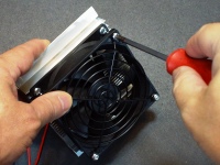
| 11. | If the fan guard has not already been installed as above, add the fan guard to the fan and attach it with the other 4 large sheet metal screws that are provided in that version of the kit.
Note: The fan guard may either be black or silver in color. |
 |
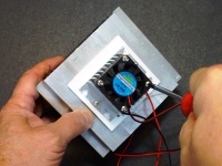
| 12. | Mount the small 40mm fan to the small heat sink.
|
 |
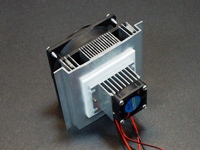
| 13. | That completes the basic assembly of the module.
Cold Side >
Hot Side > |
|
| 14. | Module Connections
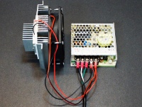
The wires from the TEC device and the fans are generally tied together and attached to the same power supply since they are all powered off 12V. This helps ensure that the fans are always operational when power is applied to the TEC device. The small 40mm fan comes with a JST style female connector which can be cut off if it is not needed. Red wires go to 12VDC, black wires go to ground. |
 |
APPLICATION NOTES:
Peltier devices in general don’t like a lot of thermal cycling as it will tend to lead to mechanical failure over time due to the continual thermal expansion and contraction. As a general rule, it is better to either operate it continually or in long cycles rather than continually cycling it on and off.
Depending on the application, it can be coupled with our W1209 or XH-W1219 temperature controller modules which can monitor the temperature and control power to the power supply used to power the TEC device. When used in this mode, it is best to allow for some temperature hysteresis on the control side to reduce the thermal cycling. The W1209 and XH-W1219 devices allow this hysteresis to be programmed.
It is also possible to drive the device at a lower voltage which produces less cooling. To this end, some controllers drive the device with PWM which is OK if it is operating at a 10hz or higher rate but that approach is less energy efficient that operating at a lower DC voltage to produce less drive. If the PWM waveform is smoothed to create a lower DC voltage, it should have less than 10% ripple and 5% is preferred for best efficiency.
OUR EVALUATION RESULTS:
These are interesting devices to work with. They do not have the cooling capacity or efficiency of large Freon based cooling systems like you find in a normal fridge, but they can be handy for small cooling tasks and are mainly designed to cool relatively small insulated spaces such as you might find with a styrofoam cooler box or chill a metal plate such as to cool a beverage that is set on it. With some tubing and creativity, it is possible to use it to cool circulating water which can then be used to cool a CPU or a race driving suit or something similar.
As can be seen in a couple of pictures, with an ambient temperature of about 65°F, the cold side heatsink reached 19.7°F with no fan on the cold side of the module. The ice formed after running overnight. With the cold side fan attached, the temperature of the heat sink increased to 43.1°F due to the fact that the fan draws air over the heat sink which cools the air and warms the heat sink. Since the humidity was fairly high, the cold heat sink surface caused some condensation to form.
BEFORE THEY ARE SHIPPED, THESE KITS ARE:
- Inspected
Notes:
- None
Technical Specifications
| Operating Ratings | ||
| DC Power Input | Typical | 12VDC |
| Operating Current | TEC1-12706 | 6A (Max), 5A (Typ) |
| Hot side 90mm Fan | 180mA | |
| Cold side 40mm Fan | 100ma | |
| Operating Power | Typical for complete assembly | 60W |
| Dimensions | W x H x D | 118 x 100 x 100mm (4.6 x 4 x 4″) |
| Country of Origin | China | |
| Datasheet | TEC1-12706 |
FURTHER READING
Wikipedia has a good overview of the technology.
Share


