
- ★Product Description
- ★About us
- ★Custom cable
Medium power transistor that can handle up to 60V @ 5A.
DESCRIPTION
The TIP120 NPN Darlington power transistor is a commonly used medium power device that can handle up to 5A @ 60V.
PACKAGE INCLUDES:
- TIP120 NPN Darlington Power Transistor
KEY FEATURES OF POWER TIP120 NPN DARLINGTON POWER TRANSISTOR:
- Medium power handling
- Up to 60V operation and 5A (8A peak) operation
- TO-220 package
These TIP120 NPN Darlington power transistors let you control quite a bit of power. They are good for up to 60V with a constant current of 5A or up to 8A peak.
The Darlington transistor architecture is actually composed of 2 transistors in an emitter-base follower configuration along with associated resistors in a single package with a BCE pin-out. This gives the transistor a much larger current gain which is useful in applications where current amplification or switching is required.
They can be used when you need to step up to an NPN transistor with more grunt than something like a PN2222 can deliver but don’t really need a big MOSFET. These are good for general purpose amplification and slower speed switching and are frequently used for driving motors, fans, high power LEDs and similar applications.
If using with an MCU, it is possible to drive the transistor directly from an output pin using a series resistor to limit current to safe levels.
OUR EVALUATION RESULTS:
While the TIP120 is considered a bit old-school, it’s a good workhorse transistor for many applications, can handle a fair amount of power and is inexpensive. It is our go-to for higher power NPN transistor  applications that we want to drive directly off an MCU pin.
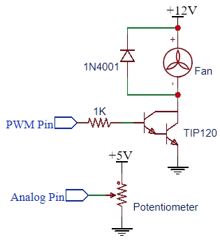
The circuit shown here uses a potentiometer to provide a variable input and a TIP120 transistor to create a variable PWM output that can be used to drive fans and small motors at variable speeds by simply adjusting the potentiometer.
Connect the wiper output of the potentiometer to the A0 analog input with the ends connected to VCC (3.3 or 5V depending on the MCU) and ground. The value is not important as it is just being used as a voltage divider and does not need to supply much current. Anything in the 1K to 50K range will work fine.
Connect the TIP120 circuit to one of the PWM output pins. We are using pin 6 in our example. The 1K resistor is used to limit the current on the output pin of the MCU to avoid any damage. Again the value is not overly important because the TIP120 has a very high gain and we just need to drive it into saturation to minimize any heating of the transistor. Something in the 270 ohm to 2.2K ohm range should be fine.
The diode across the fan is a fly-back diode used to shunt the reverse voltage that can occur when the fan or motor is turned off. This diode can be any rectifier type diode that can handle the current you are switching. The 1N4001 used in the example is good for up to 1A at up to 50V.
The fan in our example is being driven off a separate 12V power supply and the TIP120 is being used to switch the ground pin on/off using PWM to control the speed. The 12V could just as easily be 24V if using a 24V fan.
PWM Controller Software
/*
 * PWM Controller
 *
 * Reads input of pot on ADC A0 pin and prints out the raw ADC value and
 * maps it from 0-1024 to a 0-255 value and generates a PWM pulse corrosponding
 * to that value on D6.
 *
 * Useful for testing PWM drive to fans and similar items.  Be sure to use
 * driver circuit if current requirement exceeds 20mA.
 */
const int POT_PIN = A0;    // Set to analog pin being used
const int PWM_PIN = 6;     // Set to digital PWM capable pin
int ADC_Value = 0;
int PWM_Value = 0;
//===============================================================================
//  Initialization
//===============================================================================
void setup() {
  pinMode(POT_PIN, INPUT);
  pinMode(PWM_PIN, OUTPUT);
  Serial.begin(9600);
}
//===============================================================================
//  Main
//===============================================================================
void loop() {
  ADC_Value = analogRead(POT_PIN);    // Read analog value
  PWM_Value = map(ADC_Value, 0, 1023, 0, 255);  // Map to PWM value of 0-100
  analogWrite(PWM_PIN, PWM_Value);    // Update the PWM output pin value

  Serial.print("ADC Value = ");       // Print the raw ADC value
  Serial.print(ADC_Value);
  Serial.print("\t PWM = ");          // Print the calculated PWM Value
  Serial.println(PWM_Value);
  delay(1000);                        // delay 1 sec between updates
}
Notes:
- When using at higher power levels, a heat sink may be required.
TECHNICAL SPECIFICATIONS
| Maximum Ratings | ||
| VCEO | Collector-Emitter Voltage | 60V |
| VCBO | Collector-Base Voltage | 60V |
| IC | Collector Current – Continuous | 5A |
| Package | TO-220 | |
| Package Type | Plastic Tab, 3-lead, through hole | |
| Mfr | Fairchild / ON Semi/ ST Micro | |
| Datasheet | TIP120 |


